
AVR Bootloader and Programmer

The AVR109 bootloader serves as a critical component for programming FLASH memory in AVR microcontrollers using UART communication. It provides a robust framework for developers looking to implement firmware updates and manage memory efficiently. The bootloader's design allows for flexibility in application development, enabling a seamless transition between bootloader and application code. The configuration options provided by the bootloader, such as the port pin functionality, enhance user control over the programming process, making it adaptable to various hardware setups.
Furthermore, the detailed modifications suggested in the adaptation of the bootloader code highlight the importance of tailoring existing solutions to meet specific project requirements. The use of compiler directives to manage different programming sections exemplifies best practices in embedded systems development, allowing for cleaner, more maintainable code. The consideration of the Watchdog Timer as a reset mechanism is a practical approach to ensuring reliable operation during firmware updates, although it necessitates careful planning regarding its use in other application contexts.
In summary, the AVR109 bootloader represents a well-documented and versatile solution for FLASH programming in AVR microcontrollers. Its compatibility with existing programming software and the provision of sample code facilitate its integration into various projects, making it a valuable resource for engineers and developers in the field of embedded systems.Atmel`s application note AVR109 describes a bootloader that uses the UART to communicate FLASH programming instructions. They also provide some sample code in C that allows the programming of FLASH, EEPROM, and lock bits. Note that the AVR109 bootloader does not support the programming of fuses which for safety cannot be changed by the bootloader.
The communication protocol used is compatible with the AVRPROG programming software. After loading this into the bootloader section, the device can be configured so that on reset the program counter starts at the bootloader, and programmer software can program the FLASH memory. The ATMEL example bootloader program proposes the use of a port pin on the microcontroller to signal whether to execute the bootloader program or to jump directly to the application.
This allows a user to set a jumper on the microcontroller card that pulls the pin low when programming of the FLASH is needed. The adaptation of this code described here, keeps it almost unchanged in the interests of compatibility.
By disabling the port pin test and excluding the EEPROM programming section and the AVRPROG compatibility section, the code will fit neatly into a 1K block of the bootloader FLASH section on ATMega48/ATMega88/ATMega168 AVRs *. Disabling the port pin test means that on reset the microcontroller always ends up in the bootloader program (if the appropriate fuse bit has been set), and must be explicitly sent out again with a bootloader exit command.
For the moment this is acceptable as the device will normally operate while connected to a PC serial port. For standalone operation a pin will need to be made available to implement the port pin test, or the appropriate fuse bit programmed to start the device on reset at location 0.
In the latter case the application firmware will need to manage a jump to the bootloader when firmware update is required. Although the AVR109 code is freely available, Atmel has not released it under a clear open source licence.
As such the modified code will not be reproduced here. Later I may write my own bootloader or find another suitable source, however it turns out to be difficult to produce more compact C code than that provided in Atmel`s sample. There are assembler versions of the bootloader available (e. g. that by Herbert Dingfelder ) that take up less space, however assembler code is less readable and potentially less general than a higher level lenguage.
The changes made to the code are quite reasonable and simple (most are corrections to perceived minor deficiencies): Modify the block read and block write functions to add a compiler directive REMOVE_FLASH_BYTE_SUPPORT around the FLASH programming section (be careful of if-else clauses). Modify the block read and block write functions to add a compiler directive REMOVE_EEPROM_BYTE_SUPPORT around the EEPROM programming section (be extra careful of if-else clauses).
Add a compiler directive REMOVE_PROGPIN_TEST around the the port pin check section. This must also be added at the end of the "for" loop where the jump to the application is made. The preprocessor. sh script can be modified to generate an all-encompassing defines. h file covering all microcontroller types, rather than using the suggested cut and paste system. This makes use of the availability of the MMCU variable in avr-gcc to identify the microcontroller type. To allow the application to execute a jump into the bootloader I used an instruction to enable the Watchdog Timer on a very short timeout to force the MCU to be reset, the fuses being set to send it to the bootloader section.
There seemed to be a problem either with the (old) compiler or the AVR that a long jump was not possible. This has the advantage that it does not require the exact address of the bootloader to be set in the code, but of course prevents the Watchdog Timer from being used for for other purposes.
I then added code to di 🔗 External reference
Related Circuits

While lying in bed and watching movies on a laptop, the idea arose that having a remote control would simplify the tasks of pausing, playing, fast forwarding, rewinding, adjusting volume, and playing the next track without needing to approach...

An LC meter is being constructed due to the absence of a multimeter capable of measuring inductance. Although the available multimeters can measure capacitance, they lack accuracy for small capacitance values in the range of several picofarads (pF). While...

This project originated from the need to control home heating remotely from work. Utilizing a VPN connection between work and home, a relay controlled by a PC was considered the simplest solution. However, a control unit that could be...
This simple AVR programmer is capable of transferring hex programs to most Atmel AVR microcontrollers. It is more reliable than many other basic AVR programmers available and can be assembled in a short amount of time. This programmer supports...
Microcontrollers (MCUs) are versatile integrated circuits (ICs) that enhance the functionality of electronics, robotics, and various other projects. Microcontrollers serve as the brain of embedded systems, providing control, processing, and communication capabilities in a compact form factor. They typically consist...
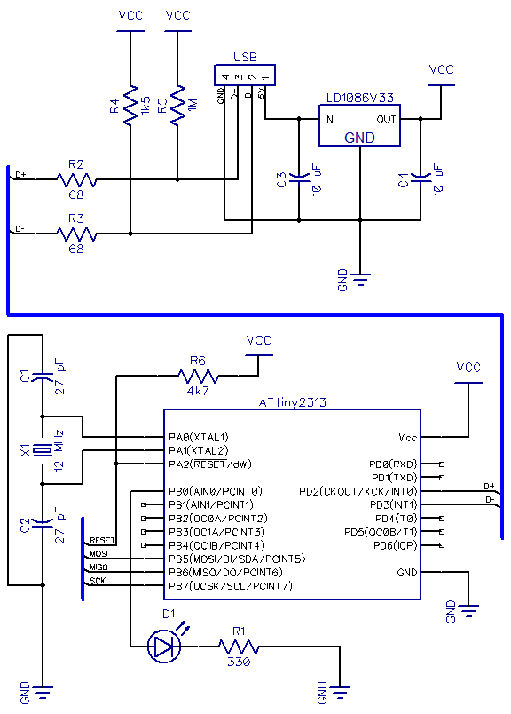
This is the second part of a USB tutorial for the ATtiny2313 microcontroller and the V-USB library. The first part covered how to derive 3.3V from USB to power circuits. In this section, the setup will be expanded with...