
Audio Wattmeter or Audio Power/Level Meter Circuit with Diagram

The audio watt meter circuit is designed to measure the output power of an audio amplifier in watts. This circuit typically employs a combination of resistive and capacitive components to accurately gauge the power level of the audio signal.
The core of the circuit consists of a voltage divider, which is used to scale down the voltage level of the audio output. This scaled voltage is then fed into a rectifier circuit, which converts the AC audio signal into a DC signal. The rectifier can be implemented using diodes, and it may include a smoothing capacitor to filter out the ripple, providing a steady DC voltage that corresponds to the audio signal's amplitude.
To measure the power, the circuit often incorporates an analog or digital meter. An analog meter may consist of a moving coil meter that displays the power level directly in watts, while a digital meter may use an analog-to-digital converter (ADC) to process the signal and display the power level on a digital readout.
Calibration of the circuit is essential to ensure accurate readings. This is typically achieved by using known power levels to adjust the scaling factors in the circuit. Additionally, the circuit may include a protection mechanism to prevent damage from high power levels, such as fuses or transient voltage suppressors.
Overall, the audio watt meter circuit serves as a valuable tool for audio engineers and enthusiasts, allowing them to monitor and optimize amplifier performance effectively. It is important to follow the schematic diagram closely during assembly to ensure proper operation and accurate measurements.A simple audio watt meter circuit or an audio power or audio level meter circuit with diagram and schematics to measure amplifier audio output power in watts.. 🔗 External reference
Related Circuits
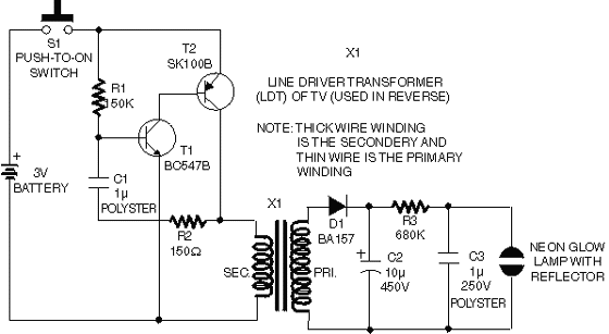
This circuit operates on 12V DC instead of mains AC. This is an advantageous approach for those who prefer not to deal with circuits connected directly to mains voltage or wish to power the stroboscope using batteries. Flash Slave...
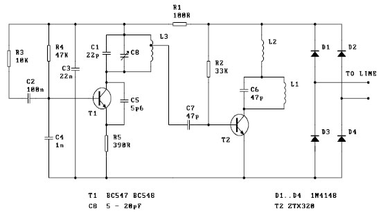
This FM spy telephone circuit is connected in series with the phone line. When there is a signal on the wires, this transmitter will radiate airwaves through the wires. This FM spy telephone circuit operates by integrating with the existing...
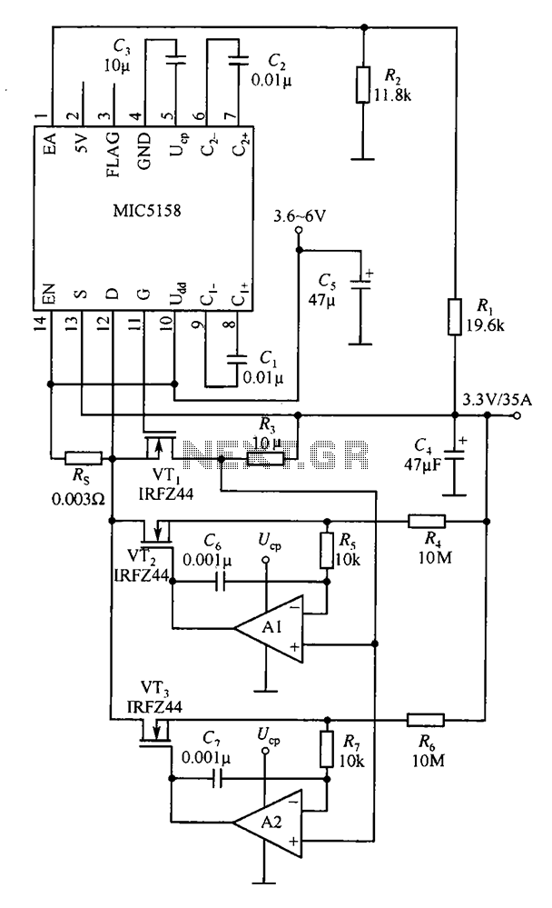
The MIC5158 is designed to manage tasks by controlling multiple external N-channel MOSFETs in parallel, which enables high current or high power output for a linear regulator circuit. This is illustrated in the accompanying figure. The operational amplifier circuit...
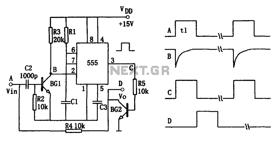
The pulse-width detection circuit is illustrated in the figure and consists of a differential circuit (R2, C2), an amplifier (BG1), a single stabilizing circuit (555, R1, C1), and various other components. The pulse signal Vin (depicted as waveform A)...
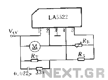
LA5522 Application Circuit. It operates as follows: When the supply voltage (Vcc) changes due to mechanical loads or negative changes, the motor speed may vary. The speed is proportional to the anti-electric potential (E), which also causes changes in...
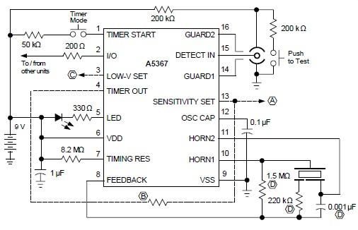
A simple ionization smoke detector with interconnect and timer alarm circuit can be constructed using the A5367 low-current, CMOS circuit, which provides all essential features for an ionization-type smoke detector. This CMOS IC, manufactured by Allegro MicroSystems, includes interconnect...