
Clock circuit circuit
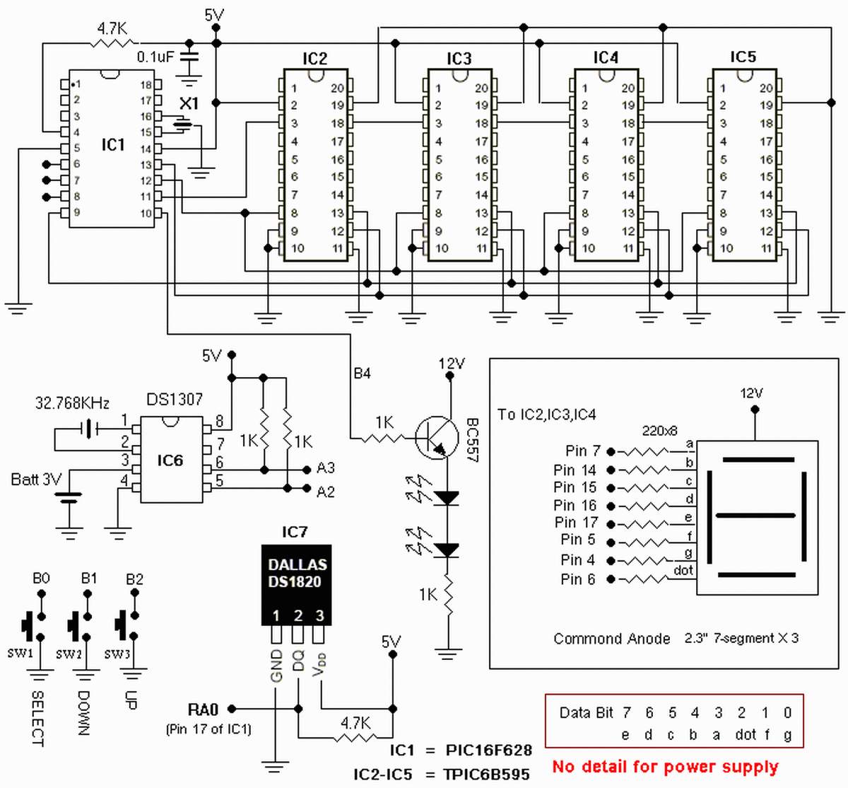
The circuit design incorporates the PIC16F877 microcontroller, a versatile 8-bit device well-suited for handling timekeeping functions. The microcontroller is responsible for decoding the MSF time signal, which is transmitted by the National Physical Laboratory in the UK. This signal provides accurate time information that the microcontroller interprets to maintain precise timekeeping.
The system utilizes twelve 7-segment displays to visually represent hours, minutes, and seconds. Each display is driven by a dedicated output from the microcontroller, allowing for simultaneous representation of time in a clear and user-friendly format. The displays are typically connected through a combination of resistors and transistors to manage current flow and ensure optimal brightness without damaging the segments.
To facilitate the decoding of the MSF signal, the circuit includes a suitable RF receiver module that captures the transmitted time signal. The microcontroller processes the incoming data, extracting the necessary information to set and update the internal clock. Additional components such as capacitors and voltage regulators may be included to stabilize the power supply and filter noise, ensuring reliable operation.
In terms of user interface, buttons may be incorporated to allow for manual adjustments, such as setting the time or toggling between 12-hour and 24-hour formats. The design may also include a power backup system, such as a battery, to maintain timekeeping during power outages.
Overall, this clock circuit exemplifies a practical application of microcontroller technology in timekeeping, combining RF signal processing with digital display management to create an accurate and visually appealing timepiece.The clock is based around a the PIC16F877 microcontroller from Microchip Technology Inc, which performs all of the logic necessary to decode the MSF signal and show the time on twelve 7-segment displays. 🔗 External reference
Related Circuits
The figure illustrates a schematic circuit of a UV sensor. When voltage is applied between the cathode and anode, and UV radiation passes through the quartz glass tube on the cathode's optical surface, the cathode material, which is coated...

Merry Company (Micrel Inc.) introduced the industry's smallest and most powerful LED driver, the MIC2298, which is widely used in portable electronic devices. The device is a 7W efficient boost DC/DC converter, packaged in a compact 3mm x 3mm...
This circuit offers an advantage over traditional continuity testing devices, which typically utilize a multimeter to assess circuit continuity. Multimeters are not suitable for testing high impedance or resistance circuits, such as transformers, capacitors, and high-value resistors. This circuit...

Battery vampires are circuits designed to extract as much energy as possible from batteries or cells. They are not regulated drivers; rather, they are boost circuits that create a higher output voltage from a low input voltage and provide...

This electronic project is a simple microphone preamplifier based on the LM318 operational amplifier. The LM318 is configured as a standard non-inverting amplifier. Resistor R1 provides a ground reference for the bias current of the non-inverting input. The combination...
It is essential to consider migrating to PIC microcontrollers and exploring compilers such as those offered by Proton Smart, which include Sony IR and Philips RC5 codecs. This approach is particularly advisable for security-sensitive applications. Additionally, Bluetooth and Wi-Fi...