
Lm318 Microphone preamplifier with tone control circuit and explanation
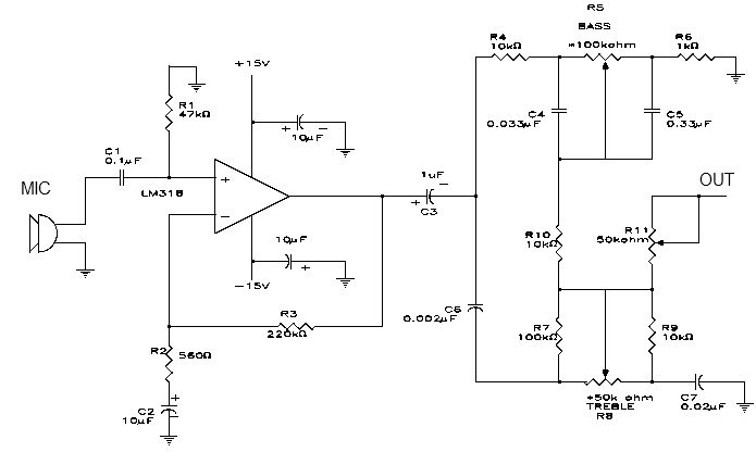
The microphone preamplifier circuit utilizes the LM318 operational amplifier, which is known for its high speed and wide bandwidth, making it suitable for audio applications. The non-inverting configuration allows for a high input impedance, which is essential for interfacing with microphones without loading them down. The biasing network, consisting of resistor R1, ensures stable operation by providing a DC path to ground, which helps maintain the input at a defined potential.
The frequency response of the circuit is tailored by the combination of R2 and C2, which introduces a high-pass filter characteristic that attenuates frequencies below 30 Hz, thus eliminating unwanted low-frequency noise. The gain of the amplifier is set by the feedback network formed by R3 and R2, allowing for a gain of approximately 50 dB, which is suitable for most microphone applications.
Capacitor C3 serves as an AC coupling element, isolating the preamplifier from the subsequent tone control section. This coupling is crucial to prevent DC offset from affecting the tone controls and ensures that only the AC audio signal passes through.
The tone control section is divided into two halves, with one half dedicated to bass control and the other to treble control. The use of audio taper potentiometers for R5 and R8 allows for a more natural adjustment of tone, as they provide a logarithmic response that aligns with human hearing perception.
The output stage of the preamplifier features a 50 k ohm potentiometer, which can be adjusted to set the final output level or gain of the preamplifier, providing flexibility for different microphone sensitivities and downstream equipment requirements.
Powering the circuit with a dual 15 volt DC supply ensures that the LM318 operates within its optimal voltage range, providing sufficient headroom for audio signals without distortion. Overall, this microphone preamplifier circuit is an efficient and effective solution for enhancing microphone signals before they are processed by further audio equipment.This electronic project is a simple microphone preamplifier based on the LM318 op amp. The LM318 op amp is operated as a standard non-inverting amplifier. Resistor R1 provides an input path to ground for the bias current of the non-inverting input. The combination of R2 and C2 provides a frequency roll-off below 30 Hz. At 30 Hz and above the gain is relatively flat at about 50 dB, set by the ratio R3/R2. R3 furnishes negative feedback from the output to the inverting input of the op amp. C3 ac couples the preamp to the tone control section. The top half of the tone control section is the bass control. The bottom half controls the treble frequency response. These tone controls (R5 and R8) require audio taper (logarithmic) potentiometers. The 50 k ohm potentiometer on the output can be used to set the output or gain of the preamp. The circuit is very simple and require few electronic parts. This microphone preamplifier electronic project must be powered from a dual 15 volt DC power supply. 🔗 External reference
Related Circuits
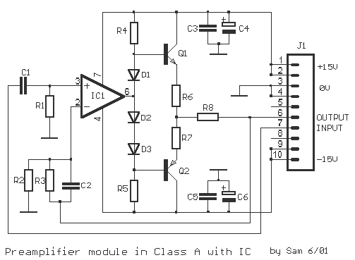
The original description discusses an application that is reputed for its high-quality sound. This superior sound quality is attributed to the operation of the entrance transistors at Class A. The sound quality is largely dependent on IC1, which needs to...

Circuit CREATOR Electronics CAE System provides the most complete and high performance solution for electronics design using personal computers. More: Includes PCB DESIGN -layout editor and Schematic Capture software tool, full Schematic Design and Capture, Circuit Simulation, full interactive...
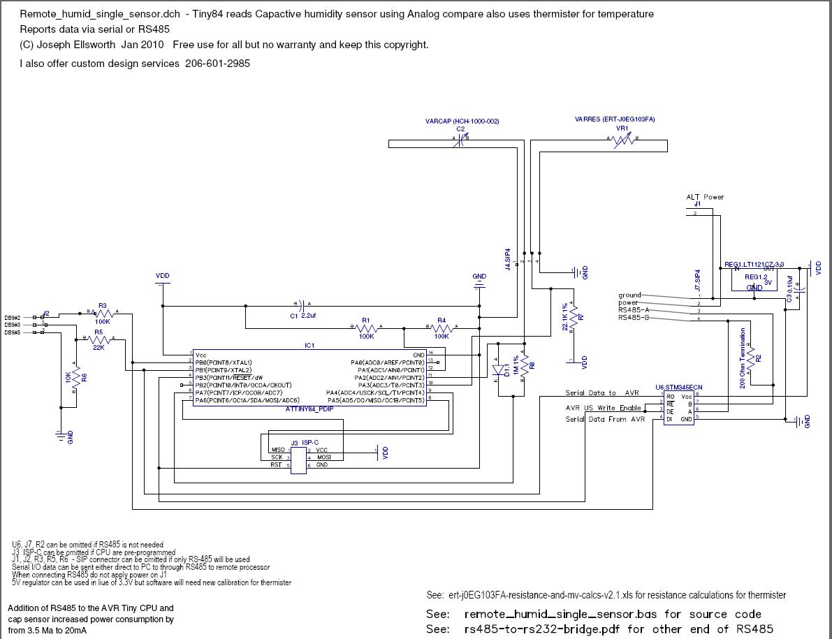
This document explains how to read a capacitive humidity sensor directly from a microcontroller using one resistor, one diode, the sensor, and two I/O lines. This method does not use an ADC but measures the time required to charge...
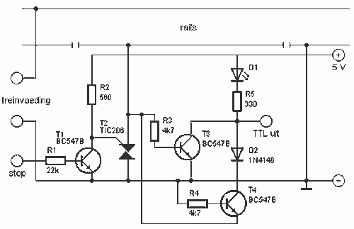
This circuit can detect whether a train is in a particular drive. The output is TTL and CMOS compatible and can be processed by such a computer. The simple circuit works. The driving voltage is connected to the two...
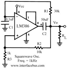
Several operational amplifier circuits are presented here, configured as square wave oscillators. A square wave is a periodic pulse train with a 50 percent duty cycle. The operational amplifier functions as a high-gain amplifier, and oscillation is achieved with...
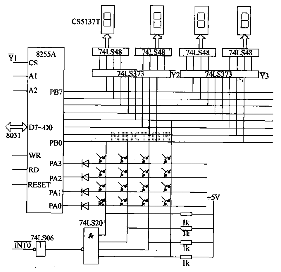
A 4x4 matrix keyboard system is designed for parameter settings, featuring numeric keys from 0 to 9 and function keys labeled A to F. The primary functions of the keyboard include completing parameter settings, selecting display modes, starting automatic...