
Function generator

When the input clamp is connected to the positive supply voltage, the capacitor charges through R1, causing the inverting input potential to increase. However, due to negative feedback, the output voltage of the operational amplifier decreases to maintain the inverting input potential at ground level. With R1's left side connected to the positive supply and the right side grounded by the operational amplifier, the voltage drop across R1 and the current through R1 and C1 remain constant. This establishes a linear relationship between the voltage across the capacitor and time, given that current and capacitance are constant values. To keep the inverting input at ground level, the operational amplifier's output voltage counterbalances the increasing capacitor potential, demonstrating a linear correlation between the slope and the resistance of R1 and the capacitance of C1. Doubling either R1's resistance or C1's capacitance halves the slope of the curve.
If the input clamp connects to the negative supply voltage, the capacitor charges with reverse polarity. The operational amplifier's output voltage increases to maintain the inverting input at ground level, starting from the negative supply voltage and increasing until it reaches the positive supply voltage. To achieve a triangular waveform, the input voltage must alternate between the positive and negative supply voltages as the output voltage approaches either supply limit. A Schmitt trigger circuit can facilitate this process: the integrator's output connects to the non-inverting Schmitt trigger's input. The Schmitt trigger's output, linked to the integrator's input, shifts to the positive supply voltage when the integrator's output reaches the upper threshold. At this point, C1 charges with reverse polarity until the integrator's output hits the lower threshold, causing the Schmitt trigger to switch to the negative supply voltage, prompting the integrator's output voltage to rise again. By incorporating three potentiometers, the output curve's shape can be adjusted; the first potentiometer modifies the Schmitt trigger's lower and upper thresholds, allowing for output curve level adjustments.
The described function generator circuit employs an operational amplifier in an integrator configuration, with a capacitor (C1) and a resistor (R1) forming the feedback loop. The operational amplifier stabilizes the input conditions through negative feedback, ensuring that the inverting input remains at the same potential as the non-inverting input, which is grounded. The feedback mechanism is crucial for maintaining the desired waveform characteristics, as it regulates the charging and discharging cycles of the capacitor based on the input voltage levels.
The integration of a Schmitt trigger enhances the circuit's functionality by providing hysteresis, which is essential for generating clean transitions between the upper and lower voltage thresholds. This feature prevents oscillations and ensures that the waveform transitions occur at precise voltage levels, thus improving the overall waveform quality. The inclusion of potentiometers allows for fine-tuning of the circuit parameters, enabling the user to customize the output waveform shape according to specific application requirements. This adaptability is particularly useful in testing and simulation environments where different waveform characteristics are needed.
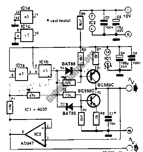
Overall, the described function generator circuit exemplifies a versatile and effective design for generating various electrical waveforms, with precise control over output characteristics facilitated by the integration of operational amplifiers, feedback components, and adjustable parameters.A device used to generate different types of electrical waveforms over a wide range of frequencies is called function generator. The most common wave forms are square, sawtooth, triangular or sine wave shapes (drawn from top to bottom).
The drawing shows an integrator circuit. There is a negative feedback provided by the capacitor, hence the poten tial at the inverting and the non inverting input is held equal by the operational amplifier. The non inverting input is connected to ground, while the inverting input is connected to the input clamp of the circuit through R1. If the input clamp is connected to ground, the difference in potential between the inverting and the non inverting input is zero volts, hence the resulting output voltage of the operational amplifier is zero volts, too.
Both plates of the capacitor are at the same potential. Furthermore both sides of the resistor are at the same potential, hence no current is running through the device and the state of the circuit is stable. If the input clamp of the circuit is connected to the positive supply voltage, the capacitor gets charged via R1, hence the potential at the inverting input would increase, but caused by the negative feedback, the voltage at the output clamp of the operational amplifier is decreasing in such a way, that the potential at the inverting input is kept at those of the non-inverting input, which it the ground level.
While the left side of R1 is connected to the positive supply voltage and the right side of R1 is kept on ground by the operational amplifier, the voltage drop across the device and so the current through R1 and C1 is constant. There is a linear correlation between the voltage across the capacitor and the time passing by. Remember that the current and the capacitance are constant values. To keep the inverting input on ground level, the output voltage of the operational amplifier is counterbalancing the increasing potential across the capacitor and there is: Derived from [9.
5], there is also a linear correlation between the slope and the resistance of R1 respectively the capacitance of C1. When doubling the resistance of R1 or the capacitance of C1, the slope of the curve gets halved. If the input clamp of the circuit is connected to the negative supply voltage, the capacitor gets charged with reverse polarity.
The voltage at the output of the operational amplifier is increasing to keep the potential at the inverting input on ground level. Starting with the negative supply voltage, the potential at the output clamp of the operational amplifier is now increasing until the positive supply voltage is reached.
The intention is to get a triangular curve progression, so all we have to do is altering the input voltage of the circuit from the positive to the negative supply voltage whenever the output voltage is close to the negative supply voltage respectively altering the input voltage from the negative to the positive supply voltage whenever the output voltage is close to the positive supply voltage. A circuit suitable for that is a Schmitt trigger : The output signal of the integrator is connected to the input clamp of the non inverting Schmitt trigger (left operational amplifier).
The output of the Schmitt trigger, which is connected to the input of the integrator, tilts to the positive supply voltage, whenever the output of the integrator reaches the upper threshold. Now C1 gets charged with reverse polarity, until the output of the integrator reaches the lower threshold.
Now the Schmitt trigger tilts to the negative supply voltage, which is why the output voltage of the integrator is increasing again. When inserting three potentiometers, the shape of the output curve can be varied. Potentiometer number one alters the lower and upper threshold of the Schmitt trigger, hence the level of the output curve can be adjusted by this device.
Potentiometer number two enables the adju 🔗 External reference
Related Circuits
Square wave tone bursts are generated by pressing the pushbutton. The duration of these bursts is determined by how long the voltage at Pin 4 exceeds a specified threshold. The circuit described involves a square wave generator that produces tone...
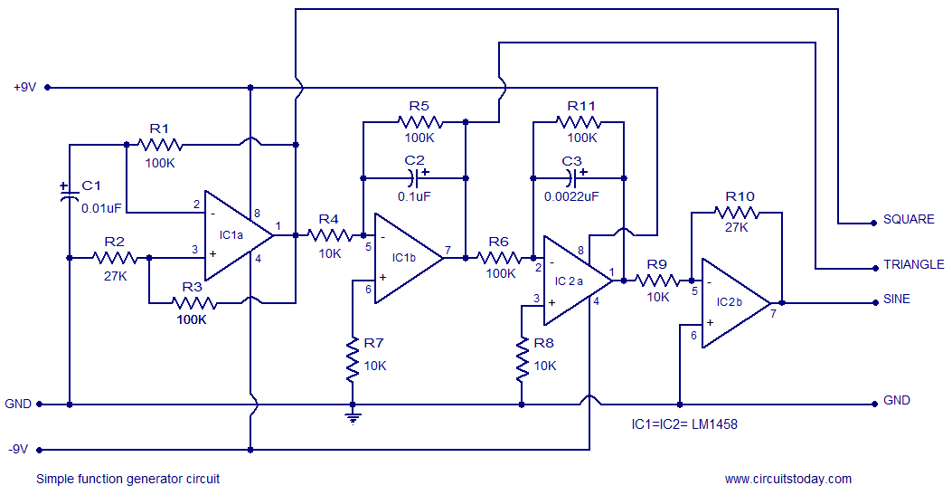
A simple function generator circuit utilizing the LM1458 is presented here. The LM1458 is a dual general-purpose operational amplifier. The two op-amps within the LM1458 share a common bias network and power supply line, yet operate independently. The function generator...
This circuit represents a simple yet accurate 1Hz timebase generator utilizing a standard quartz clock circuit board. The described circuit employs a quartz crystal oscillator, which is known for its precision in generating stable frequencies. The standard quartz clock circuit...
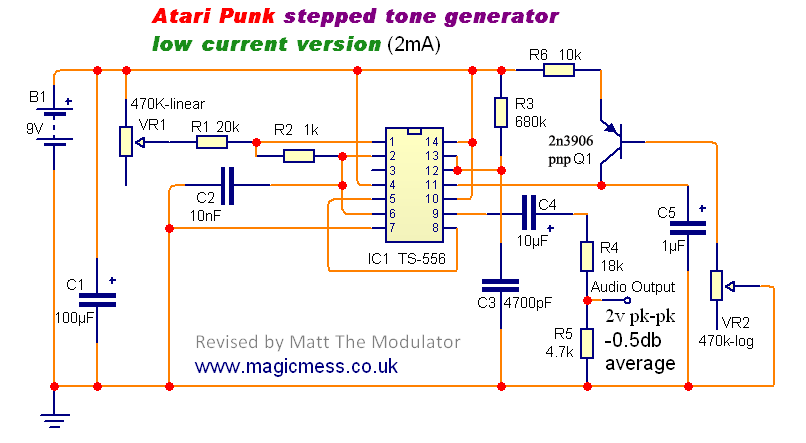
The Stepped Tone Generator is a dual oscillator circuit that produces a single pulse wave output. The first oscillator controls the pitch of the output oscillator, which divides the pitch into progressively smaller amounts based on its pulse width...
This design outlines a simple 1 kHz square wave generator utilizing a few components and the LM3909 integrated circuit, which is beneficial for testing audio equipment. The circuit operates on a single 1.5V battery cell, producing a maximum output...
This circuit attempts to liven up mono sound sources by simulating a stereo signal. It does this by shifting certain frequencies between left and right to fool the ear. It can often produce a passable mock stereo sound to...