
555 IC for Square Wave Tone Burst Generator
The circuit described involves a square wave generator that produces tone bursts upon activation of a pushbutton switch. When the pushbutton is pressed, it allows current to flow, resulting in a voltage increase at Pin 4. This voltage must exceed a defined threshold level to initiate the generation of a square wave signal. The duration of the square wave output is directly proportional to the time that the voltage at Pin 4 remains above this threshold.
To implement this functionality, a timer IC, such as the 555 timer, can be configured in monostable mode. In this configuration, the output will transition from low to high when triggered by the pushbutton. The duration of the high output state can be set by selecting appropriate resistor and capacitor values connected to the timing circuit. The resistor (R) and capacitor (C) values determine the time constant (τ = R × C), which in turn defines how long the output remains high.
Additionally, components such as a transistor may be used to amplify the square wave signal to drive a speaker or buzzer, producing an audible tone. The circuit may also include a diode for protection against reverse polarity and a capacitor for smoothing the power supply. Proper decoupling capacitors should be placed near the IC to ensure stable operation, minimizing noise and voltage fluctuations.
Overall, this circuit design allows for the generation of adjustable tone bursts, making it suitable for applications in alarms, timers, and sound effects in various electronic devices.Square wave tone bursts is provided by depressing the pushbutton. It`s duration depends on the duration for which the voltage at Pin 4 exceeds a threshold.. 🔗 External reference
Related Circuits
Here the popular 555 timing IC is wired as a monostable. The timing period is precise and equivalent to: 1.1 x R1 x C1. With component values shown this works out at approximately 1.1 msec. The output duration is...
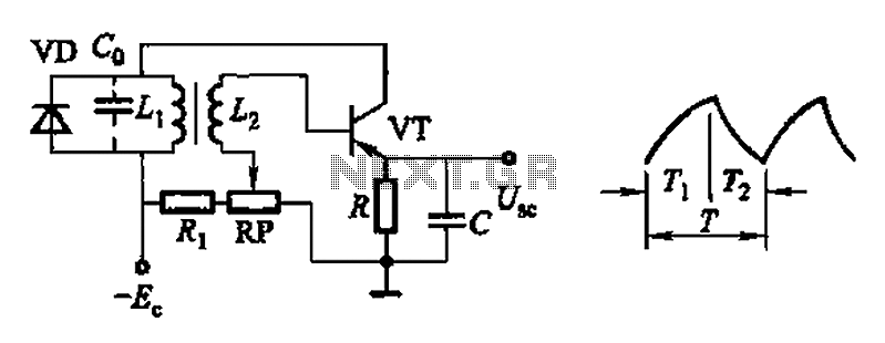
Common non-sinusoidal oscillator circuit, waveform and frequency formula - pulse wave oscillator - single-junction transistor blocking oscillator. The common non-sinusoidal oscillator circuit described is a pulse wave oscillator that utilizes a single-junction transistor in a blocking configuration. This type of...
If a negative supply is required for an operational amplifier or if a negative bias voltage is needed while operating from a single supply voltage, such as in battery applications. To generate a negative supply voltage from a single positive...
A squarer circuit is utilized to shape a signal, producing a more defined square wave. This circuit is beneficial for converting a signal to achieve a very fast rise time. The squarer circuit is designed to convert an input...
This document outlines a basic circuit designed to power high impedance, high voltage, low current devices such as electroluminescent (EL) backlights and fluorescent tubes. The project originated from the need for a simple yet flexible inverter circuit for an...
The ratio R1/R2 determines the amplitude of the triangle wave in relation to the square-wave output. The frequency of oscillation for both waveforms can be calculated using the equation: fo = 1/(4R3C1) * (R2/R1). In this circuit, R1 and R2...
Warning: include(partials/cookie-banner.php): Failed to open stream: Permission denied in /var/www/html/nextgr/view-circuit.php on line 713
Warning: include(): Failed opening 'partials/cookie-banner.php' for inclusion (include_path='.:/usr/share/php') in /var/www/html/nextgr/view-circuit.php on line 713