
Quartz 1Hz Generator
The described circuit employs a quartz crystal oscillator, which is known for its precision in generating stable frequencies. The standard quartz clock circuit board typically operates at a frequency of 32.768 kHz, a common frequency for timekeeping applications. To derive a 1Hz output from this high-frequency oscillator, a frequency divider is implemented.
The circuit can be constructed using a series of flip-flops or a binary counter, which divides the input frequency by 32,768. This division is achieved by connecting the output of the oscillator to the clock input of the first flip-flop. The output of this flip-flop feeds into the next stage, continuing until the desired division ratio is reached. The final output from the last flip-flop will produce a square wave signal at 1Hz, which can be used for various timing applications.
Additional components may include resistors and capacitors for signal conditioning and stabilization, ensuring that the output remains clean and free from noise. Power supply considerations are also critical; typically, a regulated DC power source is used to maintain consistent operation of the quartz clock circuit and associated components.
Overall, this 1Hz timebase generator is suitable for applications such as timers, clocks, and other electronic devices requiring precise timing signals. Its simplicity and accuracy make it an ideal choice for hobbyists and professionals alike.Here is one basic circuit of a simple but accurate 1Hz timebase generator built around a standard Quartz clock circuit board. Just lift the clock PCB from.. 🔗 External reference
Related Circuits
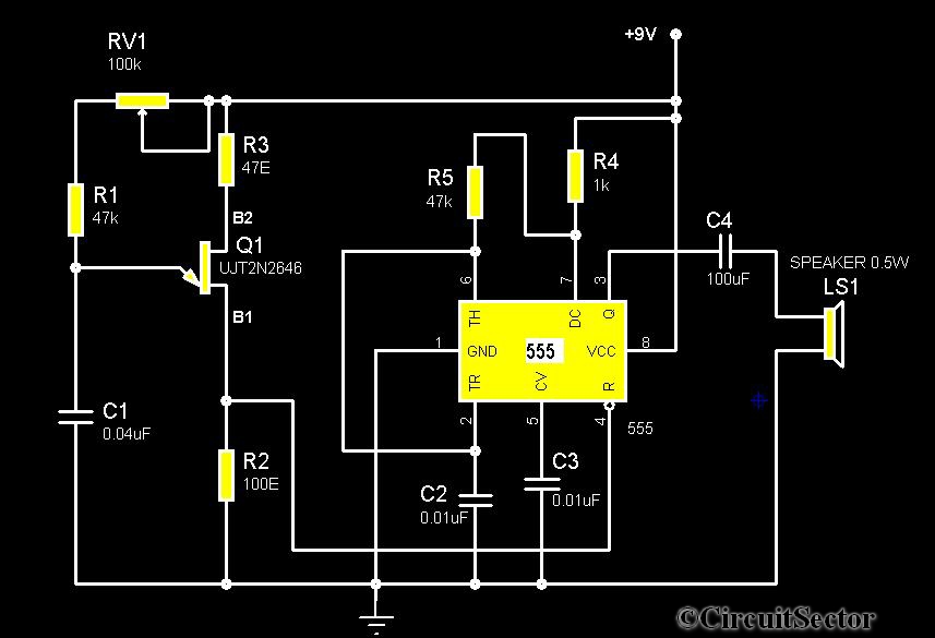
The circuit diagram illustrates a timer 555-based rain sound generator. It requires a 9V DC power supply, which can be provided by a 9V battery. The circuit utilizes a 0.5W, 8-ohm speaker to produce sound. When powered by a...
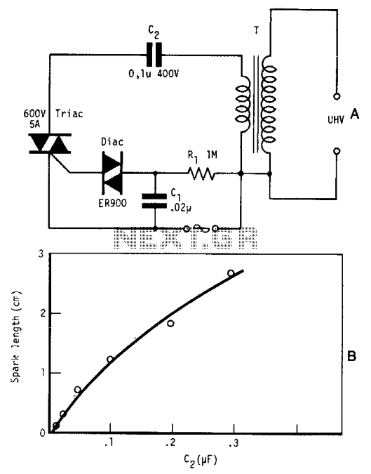
By repetitively charging and discharging a capacitor through the primary winding of an induction coil with high voltage, an ultra-high electromotive force (emf) is induced in the secondary winding. Switching is performed by a triac, which is triggered by...
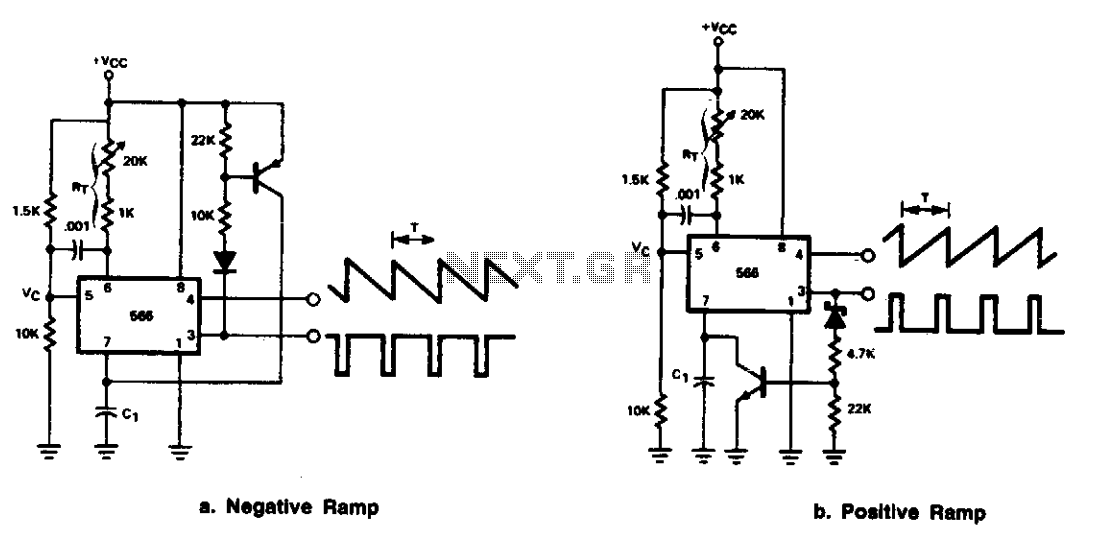
The 566 can be configured as either a positive or negative ramp generator. In the positive ramp generator configuration, the external transistor controlled by the output at Pin 3 quickly discharges capacitor C1 at the conclusion of the charging...
Most operational amplifier circuits require a dual-polarity power supply - one having +V and -V. However, there are times when a DP supply simply isn't conveniently available. Single-polarity modifications to DP designs often achieve their effect by referencing the...
A sawtooth wave generator circuit using a 555 IC is presented in the article below. The frequency equation is provided with the supply voltage Vcc. The sawtooth wave generator circuit utilizing a 555 timer integrated circuit (IC) is a fundamental...
A common requirement across various applications is a continuous signal source that produces a regular and definable waveform. Among these waveforms, the square wave is particularly significant. The circuit described utilizes a comparator featuring both positive and negative feedback...