
Atari Punk Stepped Tone Generator
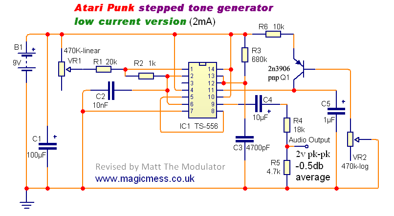
When the output is high, the voltage across R1, VR1, and R2 charges capacitor C2 until it reaches 2/3 of the supply voltage at the threshold pin (pin 2), at which point the output goes low. C2 then discharges through pin 1 (discharge). When the voltage at the threshold drops below 1/3 of the supply voltage, the trigger pin (pin 6) is activated, causing the output to go high again, initiating a self-oscillating cycle. The critical aspect of the stepped tone generator is that VR1 controls only the duration of the positive pulse; a higher resistance results in a longer positive pulse and a lower pitch, while a lower resistance yields a shorter positive pulse, resulting in a higher pitch. The duration of the negative pulse remains constant and short, which triggers the monostable pulse output. Longer negative pulses can cause the monostable to jump octaves more abruptly, and modifying the pulse width is essential for tonal character, hence keeping it short is advantageous. A negative-going trigger at pin 8 causes the output to go high, and the voltage across VR2 and R3 begins to charge C3. Once C3 reaches 2/3 of the supply voltage, the threshold triggers, setting the output low. C3 then discharges through R3 into pin 13 (discharge), which connects to ground when the output is low. The output remains low until a new negative-going pulse is received at the trigger pin (pin 8). During the high output state, the circuit ignores triggers at its input until the output returns low, thus effectively dividing the trigger signal. VR2 adjusts the pulse length by altering the time required to charge C3. As the resistance of VR2 increases, the pulse width extends beyond the frequency, causing the output to step to half the frequency of the astable oscillator. The first revision of the original circuit does not introduce significant changes but reflects a personal approach that produces preferred tones. A resistor (R1) has been added in series with VR1 to limit the charge on C2, ensuring the sound remains consistent. A 33 nF capacitor is used for the frequency of the monostable stage, allowing for less octave stepping at higher frequencies. R3 limits the current draw of the monostable stage, while R4 and R5 form a part of the circuit that is not fully detailed in the provided input.The Stepped Tone Generator is a simple dual oscillator circuit with a single pulse wave output. The first oscillator drives the pitch of the output oscillator which divides the pitch by increasingly smaller amounts as the pitch increases depending on its own pulse width (steps) setting. The name "Atari punk console" came about as some builders say the sound resemble`s that of early Atari games consoles. The original circuit shown right - is pretty raw if R1 gets to low in resistance the circuit stops and its output only suitable for a 8ohm speaker but these little points can easily be sorted. The circuit is made up of two simple circuits ~ A Astable multi vibrator (oscillator) triggering a Mono-stable (one shot pulse generator) which acts as a frequency divider and pulse width modulator.
One of the drawbacks of the original circuit is is sucks a bit of current (10 - 20mA) which is not to much on its own but once you start to add LED`s, modulators and other circuit bits your batteries don`t last very long! The purpose of this page is to look at how the circuit works why it uses so much current and how I came to adapted the circuit for a low power consumption.
(0. 5 - 1. 5mA instead of 20mA !) A schematic of this circuit is at ther bottom of the page. It is really not necessary to under stand how the 555 / 556 timer works in order to make the stepped tone generator but its worth having to understanding if you want to modify the circuit. Basically a 556 timer is a dual timer, it has to equiverlant 555 timers in one chip package IE you can make the circuit with 2 555 timers or one dual 556 timer SEE HERE for an example.
HERE is a good expanation of how the timer`s work. Below is an expanatiove of how the Stepped tone generator works scroll down for my 2 revised APC circuits. When the output is high the voltage through R1, VR1, R2 charges C2 until a voltage of 2/3rds of the supply is across the threshold pin 2, then the output goes low, C2 now discharges through pin 1 (discharge).
When the voltage across the threshold goes below 1/3rd supply voltage because the trigger pin6 is conected to the theshold pin the output now goes high and the cycle start again and again IE its self oscillates. The crucial part of this for the stepped tone generator is that VR1 controls only the positive pulse time, High resisatance = long positve pulse and therefore lower pitch and low resisance = short postive pulse IE high pitch.
The down time of the pulse is constant and short its this that trigger`s the mono stable pulse output. Long negative pulses can make the mono stable jump octave more suddenly and with pulse width change a crucial part of the tonal character its good to make it short.
A negative going trigger at pin 8 causes the output to go high The voltage through VR2 and R3 then starts to charge up C3. When the charge on C3 reaches 2/3rds the supply voltage the threshold triggers setting the output low C3 now discharges through R3 into pin 13 (discharge) which connects to ground when the output is low.
The output stays low until a new negative going pulse is received at the trigger pin8. While the output is high the circuit ignores triggers at its input until the output goes low. This is how it divides the trigger signal. VR2 controls the pulse length by changing the time it takes to charge up C3 As the resistance of VR2 is increased further the pulse width is longer than the frequency and the output steps to half the frequency of the astable oscillator. Above is my 1st revision of the original circuit its offers nothing really new its just my way of doing it and produces the tones i like.
I have added a resistor (R1) in line with VR1 to limit the charge on C2 so the sound never cuts out. I use a 33nf cap for the frequency of the Mono~stable stage it make it step down in octave less at high frequencies. R3 restricts the current draw of the Mono~stable stage. R4 and R5 form a po 🔗 External reference
Related Circuits
This circuit utilizes a CMOS chip and a VMOS FET amplifier to achieve 6 W of audio output. With a +24 Vdc power supply, it can generate up to 18 W of audio. IC1A and IC1B function as a...
This application note describes the implementation of a single-supply triangular wave oscillator using the MAX9000 integrated circuit and several passive components. The circuit employs an operational amplifier, a comparator, and a voltage reference as the main active components. The...
A 1 kHz square wave signal generator is created using a time base circuit with an NE555 timer, combined with a time constant circuit consisting of a 47 kΩ resistor and a 0.15 µF capacitor. The circuit utilizes the...
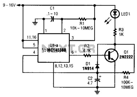
When power is first applied to the circuit, capacitor C2 begins to charge through LED1, resistor R3, and resistor R4. When the voltage across C2 reaches the input trigger level of operational amplifier U1, the output at pin 6...
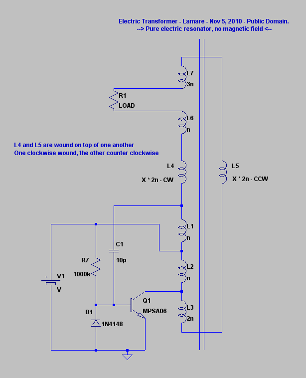
The principle involves a parasitic capacitance between coil windings that stores energy. By utilizing bifilar winding for the coil, a significantly larger voltage difference is achieved between adjacent windings, resulting in increased energy storage in these parasitic or self-capacitances....
By selecting the "ON" mode, the SilverPro© initiates the process of generating colloidal solutions using the preset parameters configured by the user. The unit always recalls the last used presets. During operation, the display alternates between the total elapsed...