
GSM Remote Control Module
The module that hosts the mobile phone is a printed circuit board measuring approximately 1.75 to 1.95 inches, equipped with two pin strips: a 3-pin strip and a 16-pin strip. The 3-pin strip connects to the power supply, providing both positive and negative power as well as the ignition control line (PWR). The 16-pin strip includes all communication signals between the GSM module and the remote control device, along with the analog section of the phones (AGND, contact 11). The pinout configuration remains consistent regardless of whether the SIM900 from SIMCom or the M10 from Quectel is being used.
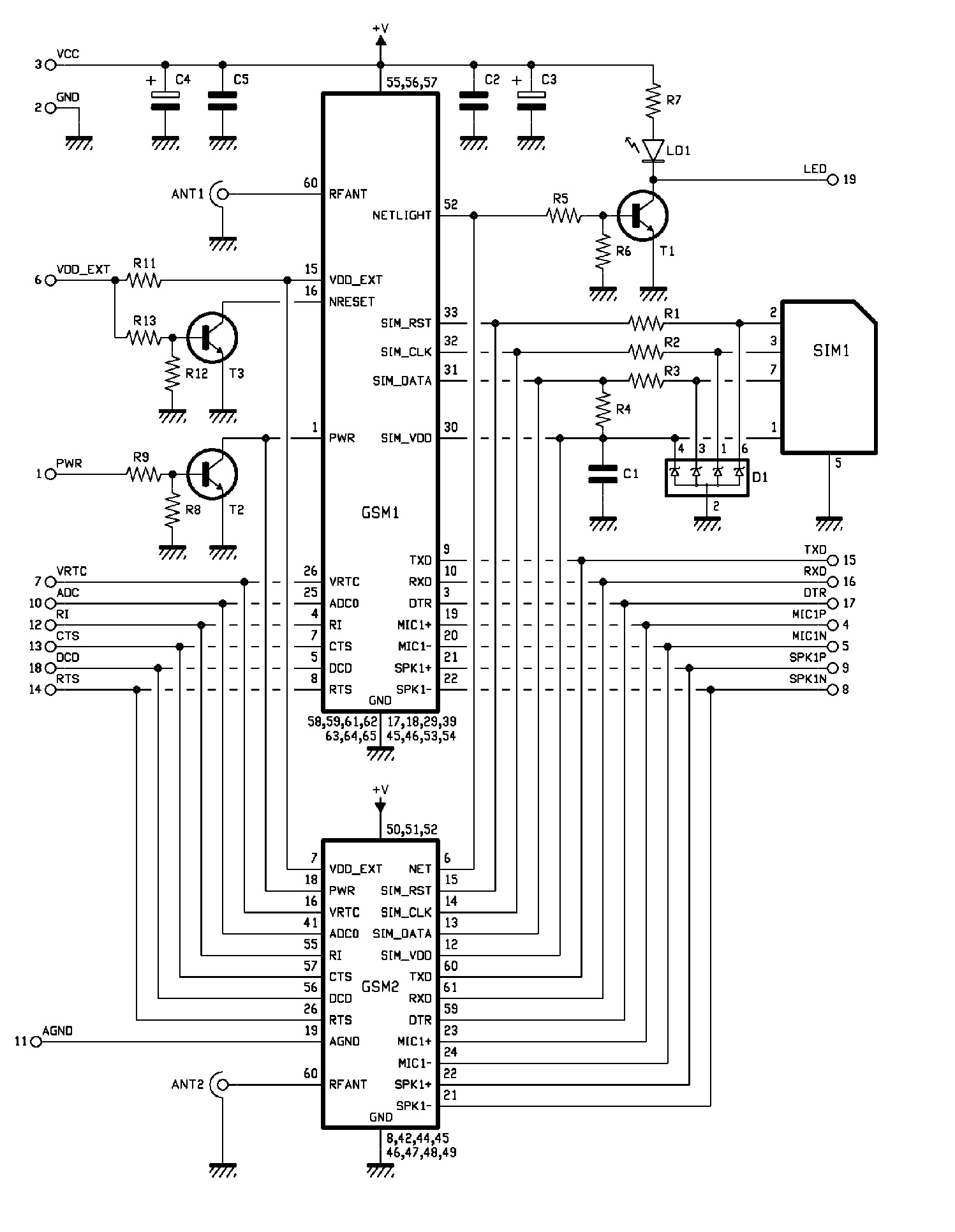
The electrical schematic illustrates the connections for both modules, noting that either GSM1 or GSM2 will be employed. The command lines for both components are largely similar, allowing the corresponding pins to be interconnected via the pin-strip contacts. The primary distinction between the two modules lies in their reset mechanisms. The SIM900 features a dedicated reset line, while the M10 requires powering down and short-circuiting the VDD_EXT line for a reset. To streamline operations, the microcontroller firmware manages both GSM modules similarly: it deactivates the main power supply and briefly short-circuits the VDD_EXT line to reset the modules.
Power management is facilitated through the PWR line, which the microcontroller uses to control the GSM module's power state. The modules are continuously powered by the Vcc line, with connections to pins 55, 56, and 57 for the SIM900 and pins 50, 51, and 52 for the M10. The modules can be toggled on or off based on the logical level applied to their PWR line (pin 1 of GSM1 or pin 18 of GSM2). The PWR line features an internal pull-up resistor and is activated at a logical zero level; thus, to power on the cellular module, the microcontroller sets PWR to a high logical level (contact 1 of the pin-strip), causing transistor T2 to saturate and pull the PWR line for both GSM1 and GSM2 to a low level.
Reset monitoring is conducted in a similar manner, although the SIM900 requires a reset input (NRESET), which is active at a logical zero and also includes an internal pull-up resistor. To reset the SIM900, the microcontroller sends a logical 1 via the VDD_EXT line, causing transistor T3 to saturate and pull the NRESET line of GSM1 to a low level, subsequently raising the module's VDD_EXT to logical 1. In contrast, the M10 does not have a reset input and can only be reset by pulling pin 7 (VDD_EXT) to logical zero after also bringing the PWR contact of the pin-strip (1) low, ensuring that transistor T2 is operational.This GSM Mobile is used for our Remote Control (for example Gate Control, Temperature Control . ). We use the word module` because, unlike what we did in ourremote control projects, this time around the mobile phone is not mounted on a printed board, but rather on a small auxiliary board which is then inserted in a connector specifically created on the main printed board; though this alternative may seem rather complex at first blush, it does have two advantages: the first is that if the GSM module should stop working, and you should not be able to find the same model, you can simply replace it with a different module without having to replace the entire circuit board. All you need to do is create a small board compatible with your unit, with the pin strips arranged as required by the circuit board.
The second advantage is that the module`s printed board is double-faced and can thus host a GSM module on one face and a different one on the other. This provides the option of choosing between two different mobile phones according to one`s needs. Let us begin by describing the module hosting the mobile phone: it is a printed circuit board measuring about 1.
75G—1. 95 inches, with two pin strips (a 3-pin one and a 16-pin one) used to connect with the circuit board of the remote control device; the first pin strip carries digital power (both positive and negative), in addition to the ignition control line (PWR), while the second strip contains all the communication signals and lines to and from the GSM module, as well as the analogical section of the phones (AGND, contact 11). This pinout remains unchanged regardless of which of the two modules (SIM900 from SIMCom or M10 from Quectel) is in use.
Let`s now take a look at the electrical scheme, which displays the connections for both modules; recall that either GSM1 or GSM2 will be used. The two components have more or less the same command lines, so the relative pins can be connected together with the pin-strip contacts.
The main differences between the two modules are found in their reset properties. SIM900 is equipped with a specific reset line, while in the case of M10 it is necessary to turn the power off and short-circuit the VDD_EXT line. In reality, in order to simplify things, the microcontroller`s firmware handles both GSM modules in the same way: in order to reset them, it turns off the main power supply and short-circuits the abovementioned line for just a second.
How is power handled The PWR line is needed by the microcontroller to turn the GSM module on and off. The modules that are used are constantly under tension, provided by the Vcc line to pins 55, 56, 57 for SIM900 and to pins 50, 51, 52 in the case of M10; these modules are turned on or off according to the logical level applied to their PWR line (pin 1 of GSM1 or pin 18 of GSM2).
The PWR line is equipped with an internal pull-up resistance and is active at logical zero; therefore, in order to switch the cellular module on, the microcontroller sets PWR at a high logical level (contact 1 of the pin-strip) and causes transistor T2 to saturate; this transistor will then sets the PWR line for both GSM1 and GSM2 at a low level. Reset monitoring is handled similarly, except that in the case of SIM900 there must be a reset input (NRESET, active at logical zero and equipped with a pull-up internal resistor), whereas in order to reset the M10 module one must resort to a little artifice.
In the first case, the module can be reset by simply causing the microcontroller to send a logical 1 via the VDD_EXT line, at which time the T3 transistor saturates and sets the NRESET line of GSM1 at a low level; when this happens, the module`s VDD_EXT is taken to logical 1. As for M10, since it has no reset input, it can only be rest by dragging pin 7 (VDD_EXT) to logical zero, after having done the same with the PWR contact of the pin-strip (1) so that transistor 2 can be in
🔗 External reference
Related Circuits
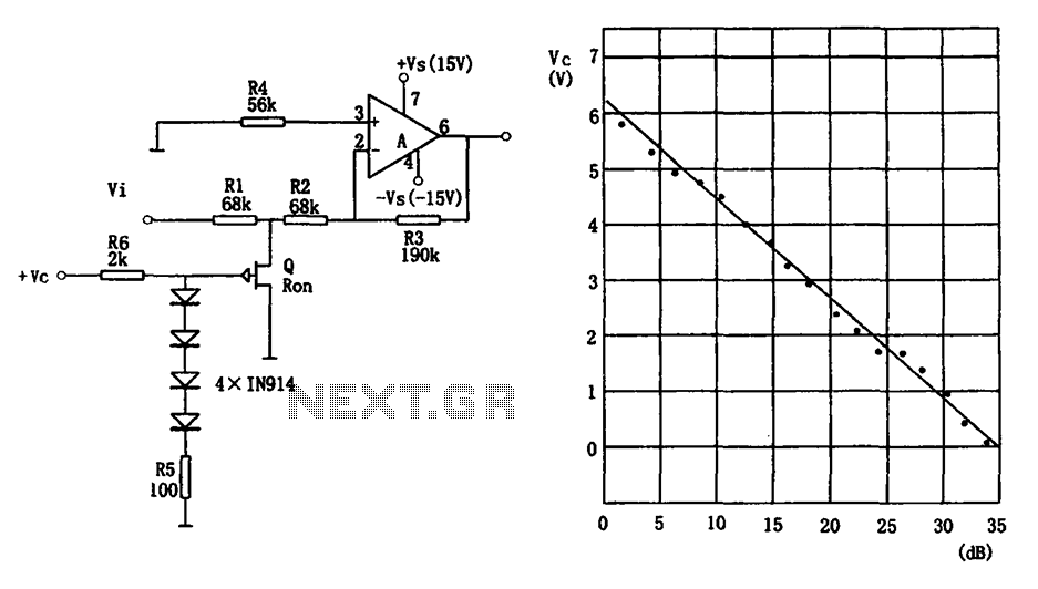
The voltage-controlled gain amplifier utilizes a FET gate voltage and the drain-source resistance (RSD) to approximate a logarithmic relationship. The integrated circuit chip LM307 is employed in the amplifier circuit with the inverting input configuration. In the circuit, RSD...
This project began with the exploration of arc starters that could be built at minimal cost using materials typically found in a tinker's workshop. Although it has been an enjoyable endeavor, the extensive collection of items in the basement...
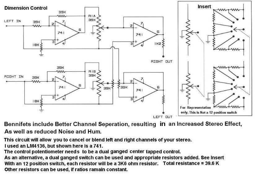
The circuit includes better channel separation, resulting in an increased stereo effect, as well as reduced noise and hum. This schematic will allow you to cancel or blend left and right channels of your stereo. Uses the LM4136 but...
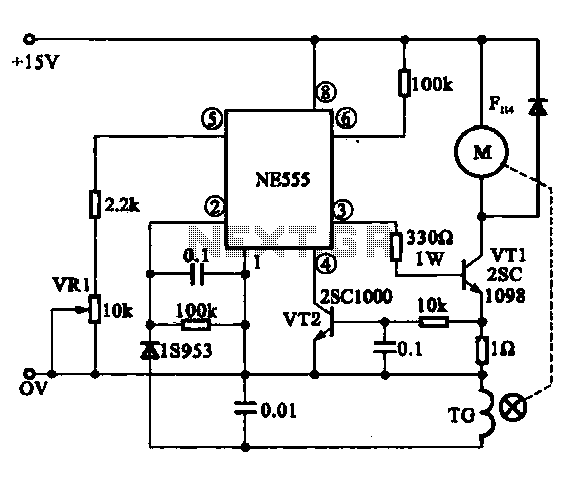
The Miniature DC Motor Speed Control circuit is designed to maintain a steady speed for micro motors, as illustrated in Figure 8-32. The circuit utilizes a voltage feedback mechanism suitable for applications such as tape recording machines that employ...
To create a versatile and generic microcontroller board, the information provided thus far is sufficient. It covers the essential components needed to achieve this. The design of a microcontroller board requires careful consideration of various factors to ensure versatility and...
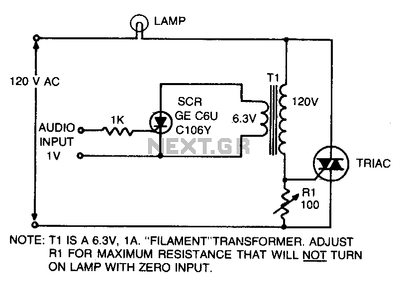
This is an on-off control with an isolated, low voltage input. The switching action occurs rapidly compared to the response time of the lamp and the human eye, resulting in an effect with audio input that resembles a proportional...