
TIG Welder and Power Control

The arc starter circuit is designed to efficiently initiate the welding arc by generating high-voltage pulses. The inclusion of Miller RC points allows for precise control over the discharge timing, essential for achieving stable arc initiation. The custom ferrite core transformer is engineered to handle high-frequency operation, ensuring minimal losses and optimal energy transfer. The multi-capacitor modules are strategically arranged to minimize parasitic inductance and enhance overall performance.
The power control section employs sophisticated techniques for managing arc welder output. The zero-crossing detection circuit ensures that SCR firing occurs at the optimal moment in the AC cycle, thereby reducing electrical noise and enhancing system reliability. The multi-pulsed gate triggering mechanism provides additional control over SCR operation, allowing for smooth transitions between power levels.
Thermal management is a critical consideration in the design. The use of aluminum heat sinks for the spark points not only facilitates effective heat dissipation but also contributes to the longevity of the components. The integration of a cooling fan further enhances thermal performance by directing airflow over both the spark points and the SCR heat sink.
The enclosure design, adapted from a computer case, reflects a practical approach to housing the complex circuitry while ensuring accessibility for maintenance and adjustments. The strategic placement of controls and indicators on the right side of the enclosure allows for intuitive operation.
Overall, this project exemplifies a blend of innovative engineering and practical problem-solving, resulting in a functional and effective arc starter and welder system. The thorough research and design efforts invested in the key components contribute to the reliability and performance of the final product.This project started from seeing pages describing arcstarters that could be constructed for practically no cost from stuff just laying around in the typical tinker`s shop. It has been a fun project, but I have a basement crammed full of stuff and I still had to spend over $600 to build the thing.
My arcstarter section runs at 300kHz, uses Miller a rc points, a homemade ferrite core coil/transformer, homemade multi-capacitor modules for the filter and tank capacitors, and generates a tremendous amount of radio-frequency interference. I guess you would say it is a typical homemade arcstarter. On the other hand, the power control section is not typical of homemade circuits. Power control is linearly contolled from zero to full power at no, partial, and full current. The circuit uses zero-crossing detection and multi-pulsed gate triggering to ensure symetrical firing of a reverse-parallel SCR module.
Making a decent looking case has always been the slowest part of a project for me. I use to have access to a metal working shop, but now I can only do it at home. So my case started as a computer case that I cut down to a size close to the size of my arc welder. The arcstarter section is on the left. I wanted to put the arc points at the rear so I could adjust them by removing a panel. Due to the available space, I had to move the arc points to the side. This location also provides a way to incorporate the ceramic tile insulator into a plenum to cool the points and keep the UV light from the point arcs away from eyes. A fan at the front cools the tank coil secondary and the MCM. The cooling air then is divided, with part flowing past the arc points, and part flowing over the heat sink for the power control SCR module.
Control of the arcstarter and the welder is on the right. A relay turns the arcstarter on and off as needed. Shielding gas is turned on and off by a a solenoid valve, and the SCR module controls the arc welder power level. The metal screen between the left and right sections is to keep the rf energy confined to the arcstarter section.
The arcstarter generates a lot of radiation that can mess up the operation of the power control board and any electronic device on the house`s electical wiring if not massively suppressed. There are four portions of the arcstarter that required research, design, and tinkering. They were the spark points, the filter capacitor, the tank capacitor, and the tank coil. Two spark point sets (four spark points) are needed to to reduce the input voltage to each set below the quench voltage at the end of each 60 Hz half-sine cycle.
Spark points have to dissipate about 30 watts of heat from the four spark points. Attempts to use 1/8" tungsten rods were not successful because the heat could not be removed from the rods to a heat sink fast enough. The result was that the gap decreased as the rods heated and the tips of the rods deteriorated. Commercial Miller spark points (PN020603 from Airgas) were too expensive, but I had to bite the bullet and purchase them.
I mounted them in heat sink holders made from 1/2" thick aluminum plate. Each point holder has two pieces 2" x 1-1/2" with three 1/2" fins cut into the 1-1/2" side. I get 27 square inches of surface for each spark point I used a 6 kv oil-ignition transformer for my high voltage source. The peak voltage on the filter capacitor should therefore be 8484 volts. I wanted at least 500 pf of capacitance and I was planning on using 1600 vdc rated capacitors. Six, . 003uf caps in series would give me 500 pf @ 9600 volts. I had planned to keep the capacitor voltage rating better than 1. 5 times the peak voltage because the capacitor rating is a vdc rating. An opportunity to very cheaply buy six, . 0056 pf capacitors rated at 2kv induced me to build a 930pf, 12kv filter capacitor. The filter capacitor and the tank capacitor both are constructed on polycarbonate frames with 1/2" spacing between
🔗 External reference
Related Circuits
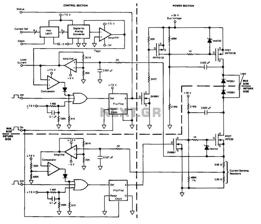
This circuit facilitates on/off switching, soft starting, current monitoring, current tripping, and overcurrent protection for a 30 Vdc power supply, accommodating normal load currents of up to 2 A. The switch is activated by an "on" command pulse and...
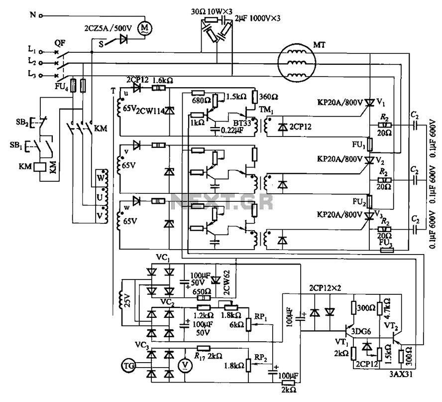
The circuit depicted in Figure 3-181 comprises three thyristors, labeled V1 to V3. The trigger circuit utilizes a single-junction transistor relaxation oscillator. The speed control circuit incorporates negative feedback. A master adjust potentiometer, designated as RPi, is used to...
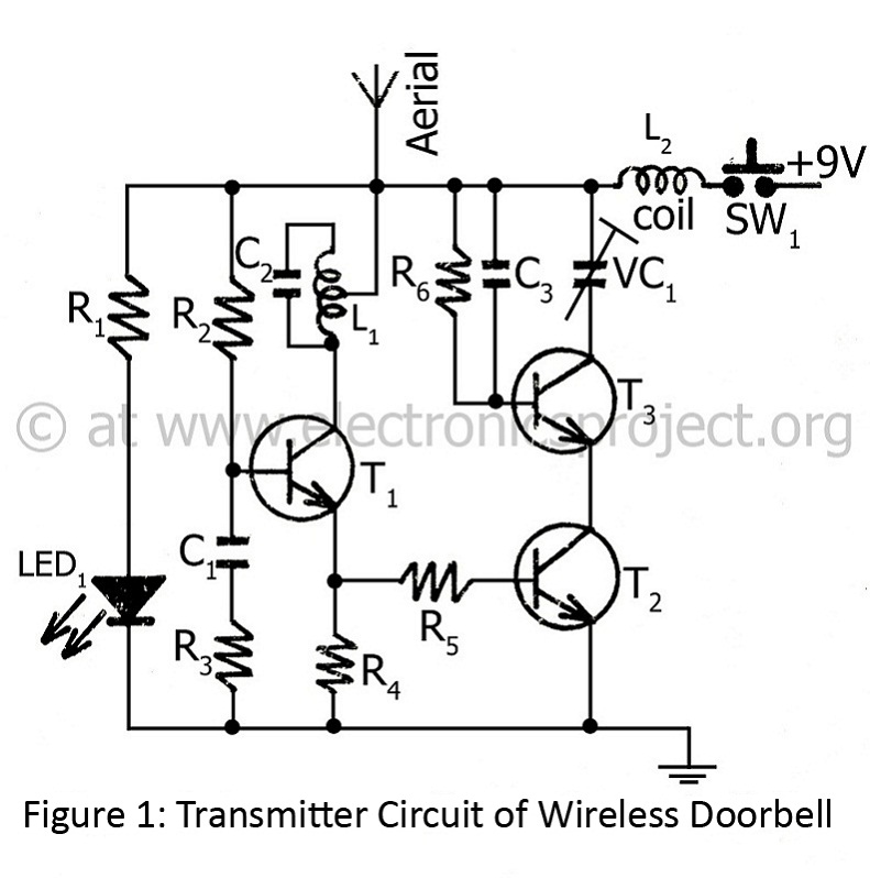
The controlling range of the wireless doorbell is 100 meters. The transmitter section is designed around an oscillator transistor (BF194B) T2, which is followed by two transistors (BC148) T1 and T3. Transistor T2 generates a specific radio frequency determined...
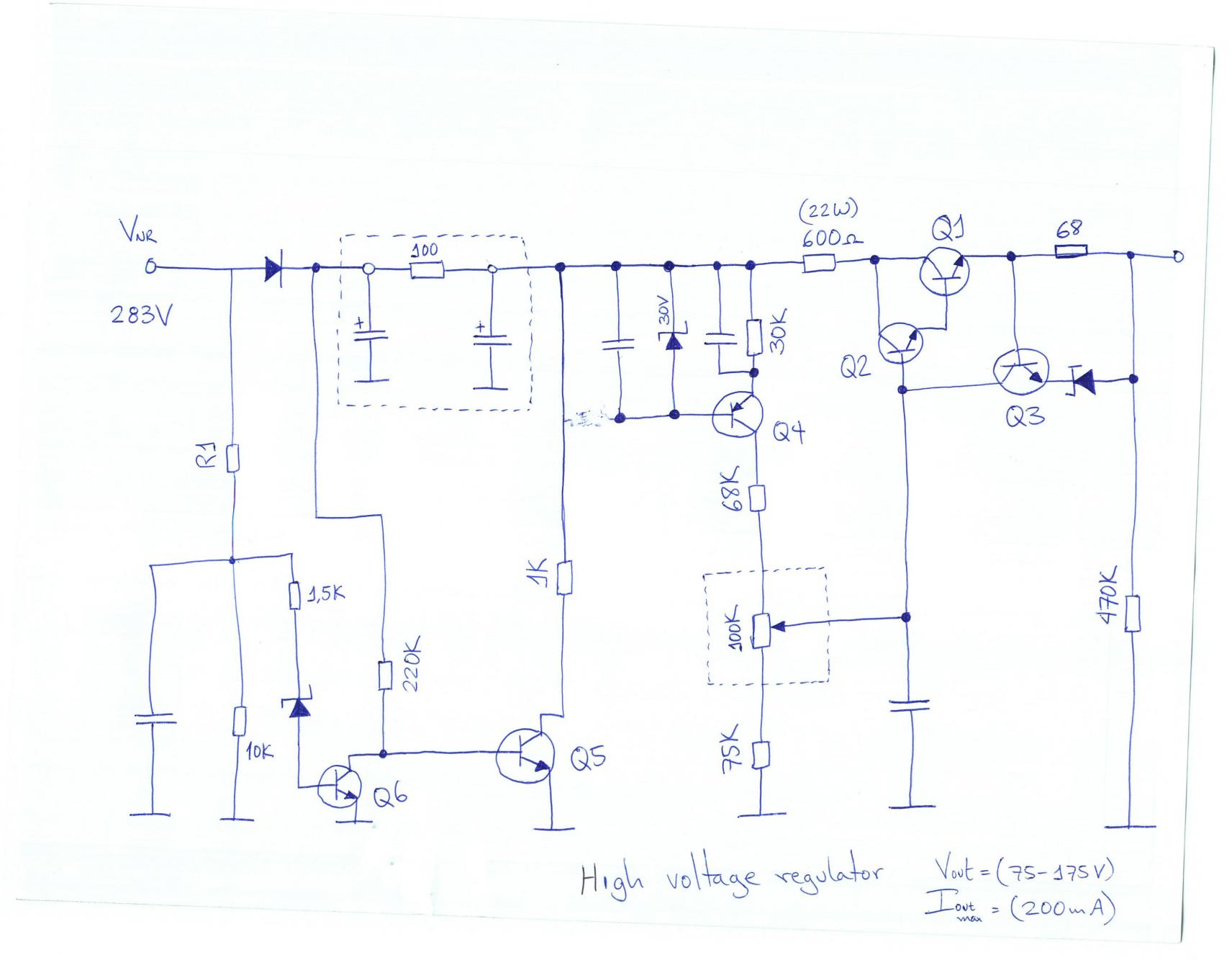
The voltage requirement for the Solidus is significantly higher than what your circuit currently provides. The Solidus device operates at a voltage level that exceeds the specifications of the existing circuit. To accommodate this requirement, circuit modifications will need to...
An exhaust fan is an essential component in kitchens. This circuit design aims to control kitchen fans by monitoring the ambient temperature. The described circuit utilizes a temperature sensor to detect the ambient temperature in the kitchen environment. When...
The principles of DC motors are discussed in the beginner and intermediate sections of this tutorial. This section will address the electronics required to interface them with a Basic X microcontroller or other digital chips. The simplest method of...