
Interfacing Electronic Circuits to Arduinos

The ARINC 429 bus plays a crucial role in avionics systems, facilitating reliable communication between various electronic components in aircraft. The bus architecture is designed to ensure data integrity and is characterized by its unidirectional nature, where data flows from a single transmitter to multiple receivers. Each device on the bus is assigned a unique label that allows for the identification of the data being transmitted. This structured approach to data communication is essential in aviation, where safety and reliability are paramount.
The interfacing process begins with selecting an appropriate ARINC 429 transceiver, which serves as the bridge between the Arduino microcontroller and the ARINC bus. The transceiver converts the digital signals from the Arduino into the ARINC 429 format and vice versa, allowing for seamless communication. The choice of a 40-pin DIP transceiver offers flexibility in circuit design and integration into existing systems.
To implement the interface, a schematic diagram would typically include the Arduino, the ARINC 429 transceiver, and the necessary passive components such as resistors and capacitors to filter signals and stabilize the power supply. The connections must be made carefully, ensuring that the data pins from the transceiver are correctly mapped to the appropriate digital pins on the Arduino. Additionally, pull-up or pull-down resistors may be required on certain lines to maintain signal integrity.
Software development is a critical aspect of this project. The Arduino IDE can be utilized to write the firmware that will control the transceiver, manage data transmission and reception, and handle any necessary data processing. Libraries specific to ARINC 429 communication may be available or can be developed to facilitate easier interaction with the transceiver. These libraries would typically include functions for initializing the transceiver, sending and receiving data, and interpreting the ARINC 429 data format.
Testing and validation of the system can be conducted using simulation tools or by connecting the setup to an existing ARINC 429 bus to monitor real-time data. This step is vital to ensure that the interface operates correctly and meets the expected performance criteria.
In conclusion, interfacing an Arduino with an ARINC 429 transceiver is a multifaceted project that combines hardware design and software development. The knowledge gained through this process can be applied to various electronic circuit designs, enhancing the understanding of data communication protocols in embedded systems.In this instructable I use an example of interfacing an Arduino to an ARINC 429 transceiver in order to demonstrate the general process of interfacing an Arduino to electronic circuits so you can use these techniques on your own designs. An ARINC 429 bus is the most common data bus used on aircraft for computer to computer communications.
The ARIN C 429 bus operates at one of two speeds, called low speed and high speed, which are 12. 5 kbps and 100 kbps respectively. The bus operates over two wires (and a ground). Each piece of data is sent in a 32 bit word. Generally the first 8 bits, called the label, are used to identify the data contained within the ARINC word. Bits 9 and 10 often define the Source/Destination Indicator, but sometimes they contain data or are an extension of the label.
Data is contained in bits 11-29 and can contain binary twos compliment, binary coded decimal, and/or a set of discrete bits. Bits 30 and 31 contain the Sign Status Matrix, and its values can indicate Normal operation, Failure Warn, No Computed Data, and Functional Test.
Finally bit 32 is the Parity bit and is set so that the 32 bit word has ODD parity. Avionics equipment manufacturers, aircraft manufacturers, and avionics equipment service centers have specialized test equipment to read these ARINC 429 data buses. I`ve wanted to own and use my own test equipment so I developed the Arinc429eReader. While this could be an instructable on its own merit, I suppose the audience interested in such a device would be small.
I will therefore present a more generally applicable instructable on the process of interfacing an Arduino to other electronic circuits. In my example I found several companies that make ARINC 429 to USB converters but they are rather expensive, $1500 US dollars or more.
There had to be a better solution. I found an ARINC 429 transceiver in a 40 pin DIP at a reasonable price. I wrote to the company and they sent me some free samples. Although the transceivers contain both a transmitter and two receivers, I only needed the receivers (at least for now!) so this chip looked good. The next step is to determine if you have the skills (and the determination) to see the project through.
To determine this I obtained the ARINC 429 transceiver chips` specification and reviewed it. What about software skills Well, I`ve done quite a bit of coding for other processors before and I can look through how other library code is written as examples of how others solved similar problems. The open source nature of Arduino is perfect for my needs here. The next step is to determine if the project should be done. It will cost money and time. I usually error on the side of trying new things for the experience if nothing else. Asking others for their opinion is often NOT recommended. Remember that most of the people we remember a great people all had contemporaries telling them they were wrong.
🔗 External reference
Related Circuits
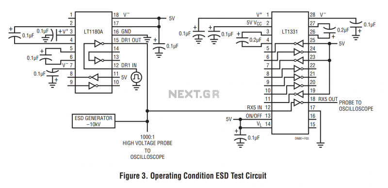
The machine model, commonly used for ESD testing in Japan, is a more severe ESD test. This model simulates metallic contact between the device under test and a charged body. The source capacitor is 200pF with no limiting resistor....
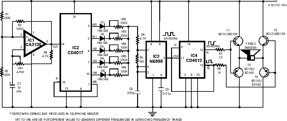
There are many ultrasonic pest repellent devices available on the market, but a major drawback is that their power output is low and their effectiveness suffers. Ultrasonic pest repellent devices utilize high-frequency sound waves to deter pests such as rodents...

Transistors are essential components of electronic circuits. The success of a circuit design depends on the selection of the appropriate transistor type and the calculations involved. Transistors serve as fundamental building blocks in electronic circuits, playing critical roles in amplification,...
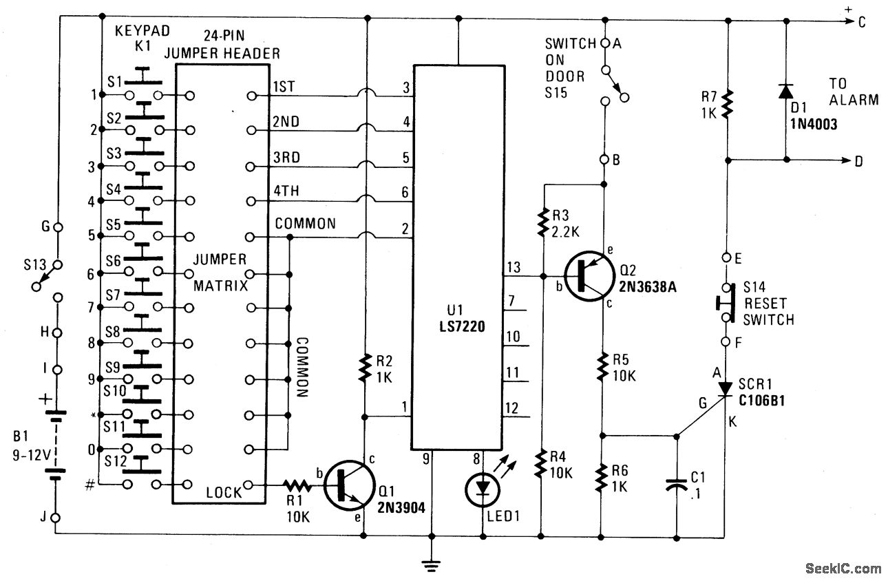
When button S12 is pressed, a positive voltage supplied through resistor R1 is applied to the base of transistor Q1, activating it. When Q1 is in the conducting state, pin 1 of U1 is connected to ground (low) or...
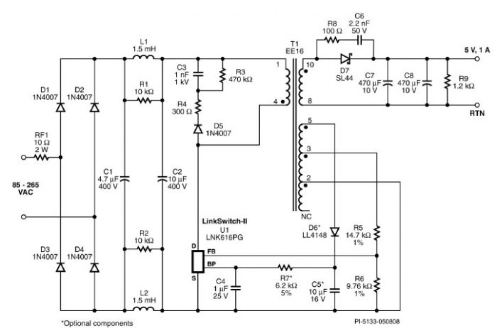
A very simple 5-volt constant voltage, constant current (CV/CC) universal-input power supply for cell phone or similar charger applications can be designed using the LNK616PG product from the LinkSwitch-II family. This low-cost charger adapter accepts a wide range of...
It is essential to consider migrating to PIC microcontrollers and exploring compilers such as those offered by Proton Smart, which include Sony IR and Philips RC5 codecs. This approach is particularly advisable for security-sensitive applications. Additionally, Bluetooth and Wi-Fi...