
ELECTRONIC COMBINATION LOCK

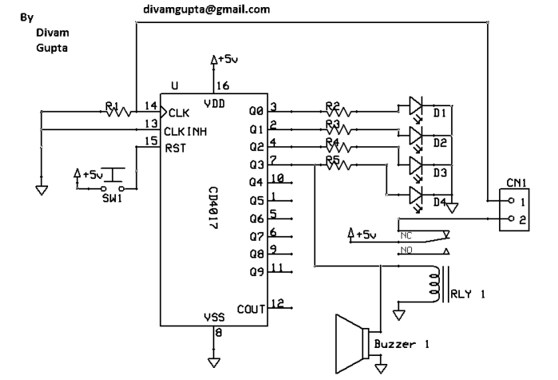
The circuit operates as a security system that utilizes a combination of transistors and an SCR (Silicon Controlled Rectifier) to detect unauthorized access through a door. The pressing of button S12 initiates the activation sequence, allowing the circuit to arm itself. The configuration of transistor Q1 ensures that when the system is armed, LED 1 provides a visual indication of the armed status.
Transistor Q2 plays a crucial role in the detection mechanism. It requires specific voltage conditions to operate effectively. The door switch S15 acts as a critical component in the security system; it remains open during normal conditions (with the door closed), preventing Q2 from turning on. When the door is opened, S15 closes, providing the necessary positive voltage to the emitter of Q1, subsequently activating Q2.
The voltage divider network formed by resistors R5 and R6 is essential for controlling the gate of SCR1. The values of R5 and R6 are selected to ensure that a sufficient voltage is present at the gate to trigger the SCR when Q2 conducts. This arrangement allows the SCR to latch on, providing a robust response to unauthorized access, which can be used to activate alarms or other security measures.
Overall, this circuit exemplifies a simple yet effective approach to security monitoring, utilizing basic electronic components to create a reliable detection system. The careful selection of resistor values and the configuration of the transistors and SCR ensure that the system operates within its intended parameters, providing both functionality and reliability in security applications.When button S12 (#) is pressed, a positive voltage fed through R1 appears at the base of transistor Q1, turning it on. When Q1 is conducting, pin 1 of U1 is brought to ground (low) or the battery`s egative terminal. With pin 1 low, two things occur: Pin 8 of U1 goes high (+9 volts dc), turning on LED 1-indicating that the circuit has been armed-an
d pin 13 goes from high to low. Transistor Q2 requires a low signal or negative voltage on its base in order to conduct. It also needs a positive voltage on its emitter and a negative voltage on the collector. As long as the door switch (S15) remains open (with the door itself closed), Q2`s emitter will not receive the necessary positive voltage. If, however, an unauthorized person opens the door, thus closing switch S15 and placing a positive voltage on the emitter of Q1, the following sequence occurs: 2.
As Q2 conducts, a voltage drop is developed across the voltage dividers made upof resistors R5 and R6. With R5 at 10, 000 ohms and R6 at 1000 ohms, approximately one volt appears at the gate of SCR1. That`s enough voltage to trigger the SCR`s gate. 🔗 External reference
Related Circuits

There are many digital thermometers with ±1°C displays, but their accuracy is approximately ±1°C and they cannot be calibrated. A thermometer circuit was created using components available at a local electronics hobby shop, providing an educational experience. For a...
The Hand Steadiness Tester is a game which tests the steadiness of your hand. The player has to take the ring from one end to another end without touching it to the wire. In this the player gets 4...

Before Light-Emitting Diodes (LEDs) and Liquid Crystal Displays (LCDs), the electronics industry utilized cold-cathode tubes for displaying numbers, symbols, and characters. Although referred to as "tubes," they differ from "radio tubes" in that they lack a heater wire to...

This project involves using an EasyDriver stepper motor driver and a 1.8-degree per rotation stepper motor to achieve a motor speed of one revolution per minute. The EasyDriver simplifies the operation, requiring a DC voltage of 7-30V connected to...
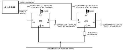
The following circuit illustrates the Ford Probe Single Wire Door Alarm System. This Single Door Locking Wire manages both LOCK and UNLOCK functions, indicating that the pulse wires must be connected to the same vehicle wire. The system primarily...
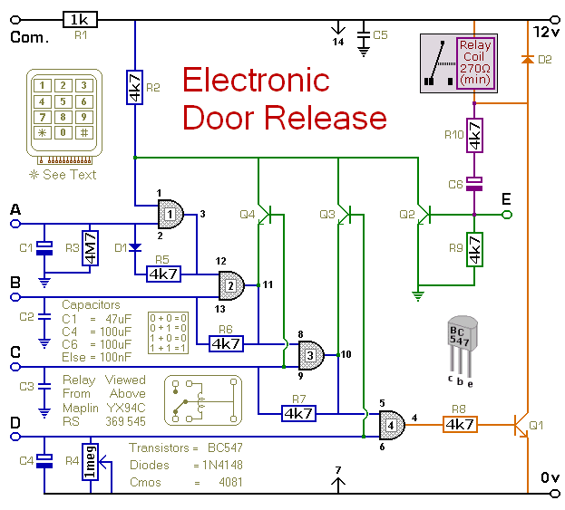
This circuit is designed to operate an electrical door-release mechanism, but it can also be used for other applications. Users can enter a four-digit code of their choice, which will energize a relay for a duration determined by the...