
Light Sensor Circuit Using Op Amp 741

The light sensor circuit operates effectively by leveraging the characteristics of the LDR and the op-amp. The LDR's resistance varies inversely with the intensity of light; as light levels drop, the resistance increases, which is critical for the functioning of this circuit. The op-amp 741 is configured in a comparator mode where it compares the voltage at pin 2 (connected to the LDR) with a reference voltage at pin 3. When the voltage at pin 2 exceeds the reference voltage, the output at pin 6 goes high, turning on the transistor Q1, which in turn activates the relay.
The inclusion of the trimmer potentiometer P1 allows for fine-tuning of the sensitivity, making it adaptable to different ambient light conditions. The use of resistors R2 and R3 in conjunction with P1 ensures that the voltage divider can be adjusted to set the threshold at which the sensor activates.
For applications requiring the reverse functionality—detecting darkness instead of light—the simple modification of swapping the LDR and resistor R1 allows for this. This flexibility makes the circuit versatile for various use cases, such as automatic streetlights or security lighting.
The addition of resistor R6 introduces hysteresis, which is essential in preventing the relay from rapidly switching on and off due to minor fluctuations in light levels. This is particularly useful in environments where light conditions may vary frequently, such as near streetlights or during twilight.
Diode D1 is crucial for protecting the circuit from voltage spikes generated when the relay contacts open, ensuring the longevity and reliability of the circuit components. The overall design operates on a 12 V DC power supply, making it suitable for integration into various electronic systems requiring low-voltage operation.This is a one of the light sensor. This circuit is a dark sensor that is based on op amp 741 IC as main control. This circuit is a simple design for sensor the light at the night. This is the figure of the circuit. For sensor the light is using LDR. Operation of the circuit is under normal conditions the resistance of the LDR is high, keeping pin 2 low. When light falls onto the LDR the resistance drops to a couple hundred ohms and triggers pin 2 high which biases the base of Q1 via pin 6 and R4 and in turn activates the relay. Trimmer pot P1 and the two 470 ohm resistors, R2 and R3, are a voltage divider to adjust for sensitivity.
If you want the action reversed (make it a dark sensor), change the positions of the LDR and R1. If the relay chatters, add a bit of hysteresis by adding a 100K to 1Meg-ohm resistor (R6) over pins 6 and 2 of the 741 op-amp, but in most cases 100K to 330K will do the job. The LDR is a regular, general purpose type. D1 serves as a spark-arrestor when the relay contacts open. This circuit power supply is using 12 V DC. 🔗 External reference
Related Circuits
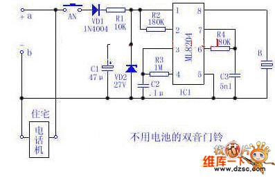
Utilize the 48V (60V) DC feedback electric current supplied by the phone feedback line as the operational energy source for the electronic doorbell, which is highly economical and practical. This document introduces a two-tone doorbell circuit that operates without...
All semiconductors exhibit the tendency to alter their fundamental characteristics in response to changes in ambient temperature. Basic electronic components such as transistors and diodes are particularly susceptible to variations in case temperature. The alteration in their characteristics is...
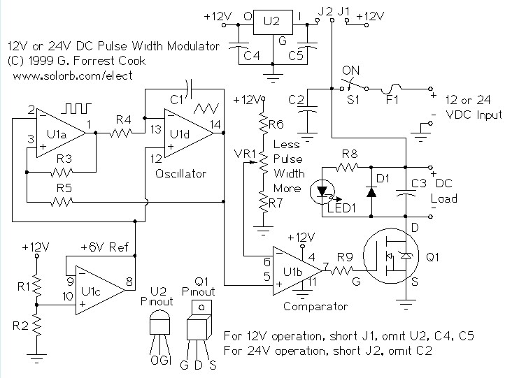
A pulse width modulator (PWM) is a device that can be utilized as an efficient light dimmer or DC motor speed controller. The circuit described here is intended for general-purpose applications, capable of controlling DC devices that draw up...
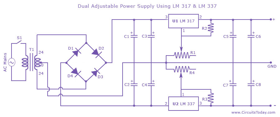
Dual adjustable power supply circuit with a diagram using IC LM317 and LM337. This variable power supply circuit has a range of 1.2 volts to 30 volts. The dual adjustable power supply circuit utilizes the LM317 and LM337 voltage regulators...
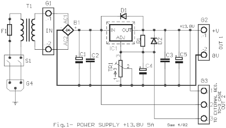
This AC to DC power supply can output 5A in continuous operation and 12A peak current. This type of DC power supply uses a PCB, allowing for two case types for IC1: TO-220 or TO-3. The regulation of this...
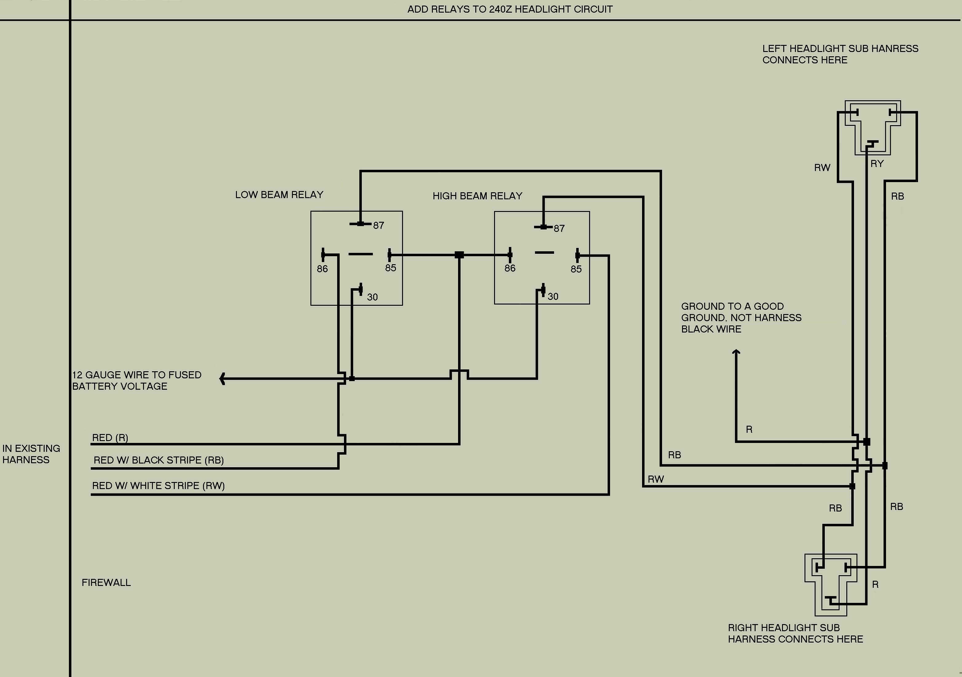
The following is a modification of the headlight wiring for 240Z vehicles. This modification is designed to reduce the current load on the headlight switch by redistributing it to two relays, thereby allowing more current to reach the lights...