
Circuit diagrams and Schematic

The project also includes a visual indicator of audio volume levels through LED lights. The LEDs can be of any color, allowing for a visually appealing display. The circuit connects to the speaker output of an audio amplifier, and it is recommended to build two identical units for both right and left channels. The input signal level is adjustable via a 10k ohm variable resistor (VR). For larger scale models, an optional output transistor can drive multiple LEDs simultaneously. The configuration lights up three LEDs for each output in a specific sequence.
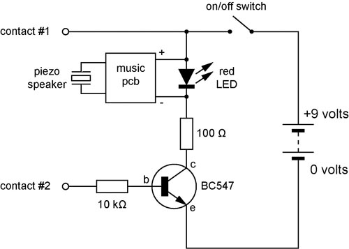
Additionally, a 555 timer is employed as the basis for a touch switch. Upon touching the plate, the 555 timer is triggered, causing the output on pin 3 to go high, activating the LED and buzzer for a predetermined duration based on the capacitor and resistor values connected to pins 6 and 7. The 10M resistor on pin 2 enhances the circuit's sensitivity to touch.
The circuit also addresses the complexities of operating systems for PCs, noting the variety of available systems and the challenges of hardware and software compatibility. A hardware solution is proposed for managing dual operating systems, utilizing the IDE specification feature called Cable Select. This allows for the two hard disk drives to swap places upon startup, appearing as though they have changed positions from the computer's perspective. The circuit connects to the IDE bus of the motherboard, interfacing with two hard disks. Upon startup or reset, a pulse on the RESET line of the IDE interface triggers a flip-flop IC, determining the master/slave configuration of the hard disks based on the state of a switch. This configuration ensures that one hard disk acts as the master drive, while the second remains inactive, facilitating seamless operation and reducing the potential for software conflicts during system boot.This ac to dc power supply can output 5A in continous operation and 12A peak current. This kind of dc power supplies uses a PCB so you can use two case types for IC1, TO-220 or TO-3. The regulation of this 12 volt power supply is made with TR1 ( multiturn ). IC1 must be placed on proper heatsink. Switching power supply whose output voltage is appr eciably lower than its input voltage has an interesting property: the current drawn by it is smaller than its output current. However, the input power (UI) is, of course, greater than the output power. There is another aspect that needs to be watched: when the input voltage at switch-on is too low, the regulator will tend to draw the full current.
When the supply cannot cope with this, it fails or the fuse blows. It is, therefore, advisable to disable the regulator at switch-on (via the on/off input). until the relevant capacitor has been charged. When the regulator then starts to draw current, the charging current has already dropped to a level which does not overload the voltage source. The circuit in the diagram provides an output voltage of 5 V and is supplied by a 24 V source. The regulator need not be disabled until the capacitor is fully charged: when the potential across the capacitor has reached a level of half or more of the input voltage, all is well.
This is why the zener diode in the diagram is rated at 15 V. Many regulators produced by National Semiconductor have an integral on/off switch, and this is used in the present circuit. The input is intended for TTL signals, and usually consists of a transistor whose base is accessible externally.
This means that a higher switching voltage may be applied via a series resistor: the value of this in the present circuit is 22 k. When the voltage across the capacitor reaches a level of about 17 V, transistor T1 comes on, whereupon the regulator is enabled.
I like to see lights move to music. This project will indicate the volume level of the audio going to your speakers by lighting up LEDS. The LEDS can be any color so mix them up and really make it look good. The input of the circuit is connected to the speaker output of your audio amplifier. You want to build two identical units to indicate both right and left channels. The input signal level is adjusted by the 10k ohm VR. If you wish to make a very large scale model of this unit and hang it on your wall there is an optional output transistor that can drive many LEDS at once. The unit I built drove three LEDS for each output. The sequence of the LEDS lighting are as follows Pin 1, 18, 17, 16, 15, 14, 13, 12, 11, 10. This circuit uses a 555 timer as the bases of the touch switch. You can learn more about 555 timers in the Learning section on my site. When the plate is touched the 555 timer is triggered and the output on pin 3 goes high turning on the LED and the buzzer for a certain period of time.
The time that the LED and the buzzer is on is based on the values of the capacitor and resistor connected to pin 6 & 7. The 10M resistor on pin 2 causes the the circuit to be very sensitive to the touch. In the last few years, the available range of operating systems for PCs has increased dramatically. Various free (!) operating systems have been added to the list, such as BeOS, OpenBSD and Linux. These systems are also available in different colours and ¬‚avours (versions and distributions). Windows is also no longer simply Windows, because there are now several different versions (Windows 95, 98, ME, NT, XP, Vista and 7).
Computer users thus have a large variety of options with regard to the operating system to be used. One problem is that not all hardware works equally well under the various operating systems, and with regard to software, compatibility is far from being universal. In other words, it`s difficult to make a good choice. Switching from one operating system to another that`s a risky business, isn`t it Although this may be a bit of an exaggeration, the safest approach is still to install two different operating systems on the same PC, so you can always easily use the old` operating system if the new one fails to meet your needs (or suit your taste).
A software solution is often used for such a dual system`. A program called a boot manager` can be used to allow the user to choose, during the start-up process, which hard disk will be used for starting up the computer. Unfortunately, this does not always work ¬‚awlessly, and in most cases this boot manager is replaced by the standard boot loader of the operating system when a new operating system is installed.
In many cases, the only remedy is to reinstall the software. The solution presented here does not suffer from this problem. It is a hardware solution that causes the primary and secondary hard disk drives to swap places` when the computer is started up, if so desired. From the perspective of the computer (and the software running on the computer), it appears as though these two hard disks have actually changed places.
This trick is made possible by a feature of the IDE specification called CableSelect`. Every IDE hard disk can be con ¬gured to use either Master/Slave or CableSelect. In the latter case, a signal on the IDE cable tells the hard disk whether it is to act as the master or slave device. For this reason, in every IDE cable one lead is interrupted between the connectors for the two disk drives, or the relevant pin is omitted from the connector.
This causes a low level to be present on the CS pin of one of the drives and a high level to be present on the CS pin of the other one (at the far end of the cable). The circuit shown here is connected to the IDE bus of the motherboard via connector K1. Most of the signals are fed directly from K1 to the other connectors (K2 and K3). An IDE hard disk is connected to K2, and a second one is connected to K3. When the computer is switched on or reset, a pulse will appear on the RESET line of the IDE interface.
This pulse clocks ¬‚ip- ¬‚op IC1a, and depending on the state of switch S1, the Q output will go either high or low. The state on the Q output is naturally always the opposite of that on the Q output. If we assume that the switch is closed during start-up, a low level will be present on D input of IC1a, so the Q output will be low following the reset pulse.
This low level on the Q output will cause transistor T1 to conduct. The current flowing through T1 will cause LED D1 to light up and transistor T2 to conduct. The hard disk attached to connector K2 will thus see a low level on its CS pin, which will cause it to act as the master drive and thus appear to the computer as the C: drive. A high level will appear on the Q output following the reset pulse. This will prevent T3 and T4 from conducting, with the consequence that LED D2 will be extinguished and the hard disk attached to connector K3 will see a high level on its CS pin.
For this disk, th. 🔗 External reference
Related Circuits
A continuity tester is useful for verifying that there is a conductive path between two points. This circuit offers the advantage of being highly sensitive, providing both visual and audible indications of continuity. An audible tester is particularly beneficial...
This circuit operates as a 9V DC power source supplying a 555 timer to generate a square wave. The output is then processed through a Half-Wave Series Multiplier (Villard Cascade) to achieve a high voltage DC output. The goal...
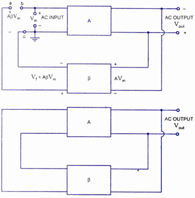
A feedback amplifier with a closed-loop gain, Af, greater than unity can be achieved through the use of positive feedback. This condition also fulfills the phase requirement, leading to the operation of an oscillator circuit. An oscillator circuit generates...
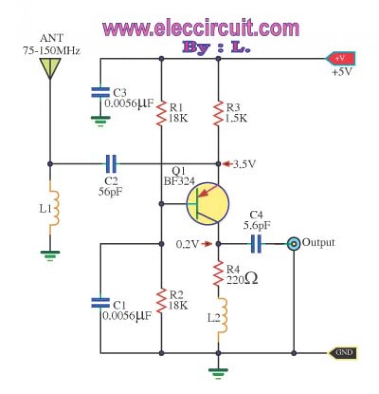
This is a wideband high-frequency amplifier circuit designed for a frequency range between 75-150 MHz. It utilizes a PNP transistor amplifier to enhance signal strength before it reaches the receiver of devices such as phones, FM radios, or amateur...
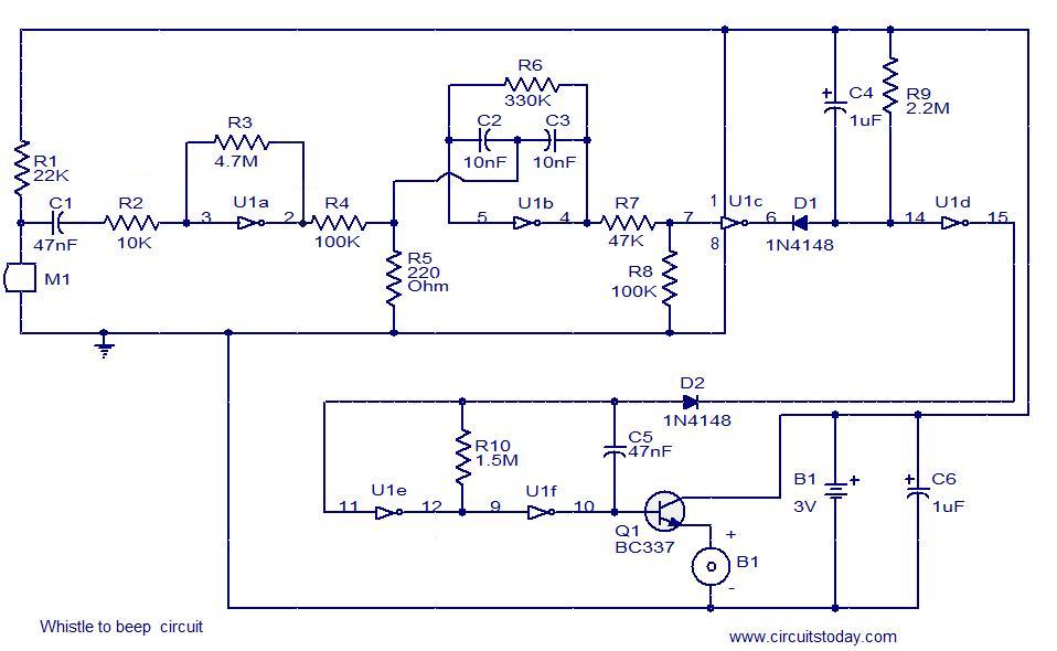
This simple circuit produces a beeping sound that lasts for approximately 3 seconds whenever a whistle is made. The CMOS Hex inverter CD4049 serves as the core component of this circuit. Among the six inverters in the CD4049, U1a...
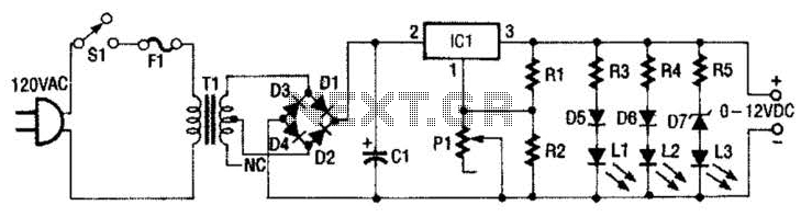
This 0- to 12-Vdc variable power supply utilizes an integrated circuit (IC) voltage regulator along with a robust transformer to deliver a dependable DC power output. The schematic illustrates that transformer T1 has a primary voltage of 120 V...