
PWM Motor Speed Controller / DC Light Dimmer
The PWM circuit operates by varying the width of the pulses in a signal to control the amount of power delivered to a load. This is accomplished through a method known as duty cycle modulation, where the ratio of the "on" time to the total cycle time is adjusted. By changing the duration of the "on" state relative to the "off" state, the average voltage and current supplied to the load can be effectively controlled, resulting in dimming for lights or speed control for motors.
Typically, a PWM circuit consists of several key components: a microcontroller or timer IC to generate the PWM signal, a power transistor or MOSFET to switch the load, and additional passive components such as resistors and capacitors for filtering and stability. The microcontroller is programmed to adjust the duty cycle based on user input or predefined settings, allowing for precise control over the output.
For a 12 or 24 Volt system, the circuit configuration will require appropriate selection of the power transistor to handle the maximum current load. For example, an N-channel MOSFET is often used due to its efficiency and fast switching capabilities. The gate of the MOSFET is driven by the PWM signal, which can be generated by a microcontroller or a dedicated PWM IC.
In terms of wiring changes for different voltage systems, the primary consideration is ensuring that the components selected can handle the voltage and current levels without overheating or failing. The input voltage should be connected to the drain of the MOSFET, while the source connects to the load, which in turn connects to ground.
Additional components may include a flyback diode across inductive loads, such as motors, to protect the circuit from voltage spikes generated when the load is switched off. Filtering capacitors may also be included to smooth out the output voltage and reduce electrical noise.
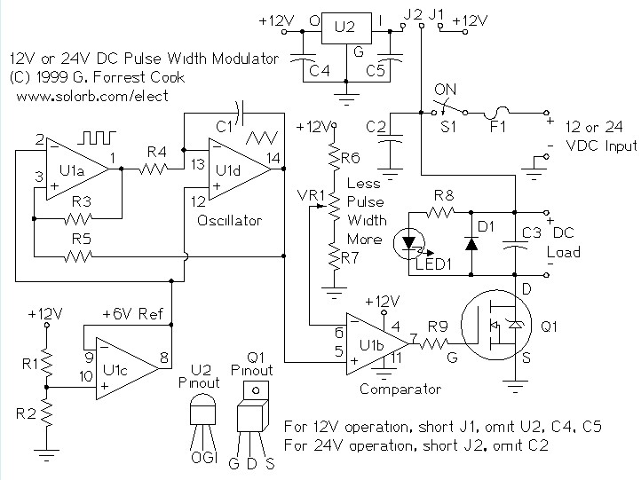
Overall, this PWM circuit provides a versatile solution for controlling DC devices, making it suitable for various applications in lighting and motor control, with the flexibility to adapt to different voltage systems with minimal modifications.A pulse width modulator (PWM) is a device that may be used as an efficient light dimmer or DC motor speed controller. The circuit described here is for a general purpose device that can control DC devices which draw up to a few amps of current.
The circuit may be used in either 12 or 24 Volt systems with only a few minor wiring changes. This device has been.. 🔗 External reference
Related Circuits
The automobile interior lights fader circuit diagram is designed to gradually brighten and dim the interior lights of older vehicles. This circuit utilizes the LM324 low-power operational amplifier as its core component. The automobile interior lights fader circuit is an...
Any stepper motor can function as a generator. Unlike other types of generators, a stepper motor generates a significant induced voltage even at low rotational speeds. The specific model used here has a DC resistance ranging from 2 ohms...

This simple pulse width modulation (PWM) DC motor control addresses common issues by regulating motor speed through the application of short pulses. The duration of these pulses is varied to adjust the motor speed; longer pulses result in faster...
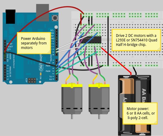
Motor shields functioned effectively; however, they are priced around $50 each, which is more than the cost of the Arduino itself. While this is acceptable for a single unit, it presents a challenge for an Arduino workshop aimed at...
The power supply section is the important one. It should deliver constant output regulated power supply for successful working of the project. A 0-12V/500 mA transformer is used for this purpose. The primary of this transformer is connected in...
The full-wave phase control circuit described was sourced from an RCA power circuits book published in 1969. In this configuration, the load is connected in series with the AC line, while four diodes are utilized to provide a full-wave...