
Long range AM transmitter

This long-range AM transmitter circuit is designed to operate efficiently using three transistors, which provide both modulation and amplification of the audio signal. The primary component, Q1, serves as the modulator where the audio signal is applied. The audio driver transformer T1 is crucial as it ensures that the audio signal is appropriately matched to the base of Q1 for optimal modulation. The collector of Q1 outputs the modulated signal that carries the information of the audio input.
To adjust the frequency of the transmitted signal, the gang condenser C7 can be tuned. This tuning capability is essential for ensuring that the transmitter operates on the desired frequency, which can be critical for avoiding interference with other signals and for compliance with transmission regulations.
Transistors Q2 and Q3 function as amplifiers, enhancing the strength of the modulated signal. They are configured in parallel to maximize the power output, which is vital for achieving a transmission range of up to 2 kilometers. This configuration allows for increased current handling and improved efficiency.
The coupling of the modulated signal to the antenna is facilitated by capacitor C4, which blocks any DC component while allowing the AC modulated signal to pass through. This ensures that only the intended modulated signal is transmitted, enhancing the quality of the broadcast.
The resonator F1 is a critical component in the circuit as it determines the frequency characteristics of the transmitter. The choice of a two-terminal resonator without a ground pin simplifies the design but requires careful handling to ensure proper functionality. If a three-terminal resonator is selected, the ground pin needs to be connected to the circuit's ground to maintain stability and performance.
Overall, this circuit exemplifies a straightforward approach to building a long-range AM transmitter, making it accessible for hobbyists and engineers interested in radio frequency transmission. Proper assembly, tuning, and component selection will yield a functional transmitter capable of long-distance audio broadcasting.Here is the circuit diagram of an easy to build long range AM transmitter circuit based on three transistors. With correct tuning and a matching antenna, the transmitter can deliver signals up to a distance of 2 kilometers.
The audio signal to be transmitted is given to the base of the transistor Q1 via the audio driver transformer T1. The modulated signal is developed at the collector of transistor Q1. The frequency of the transmitted signal can be tuned adjusting the gang condenser C7. The required amplification of the modulated signal is done by the two transistors Q2 and Q3. The two transistor amplifier stages are connected in parallel for obtaining maximum power. The signal to be transmitted is coupled to the antenna via the capacitor C4. The resonator F1 used here is a two terminal type without a ground pin. If you are using a three terminal one, the ground pin must be connected to the circuit`s ground. 🔗 External reference
Related Circuits
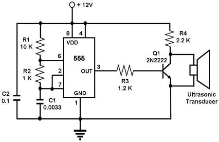
The circuit utilizes a 555 timer integrated circuit (IC) configured as an astable multivibrator, which generates a continuous signal at a specific frequency as long as its reset pin (pin 4) is held high. The ultrasonic transducer employed in...
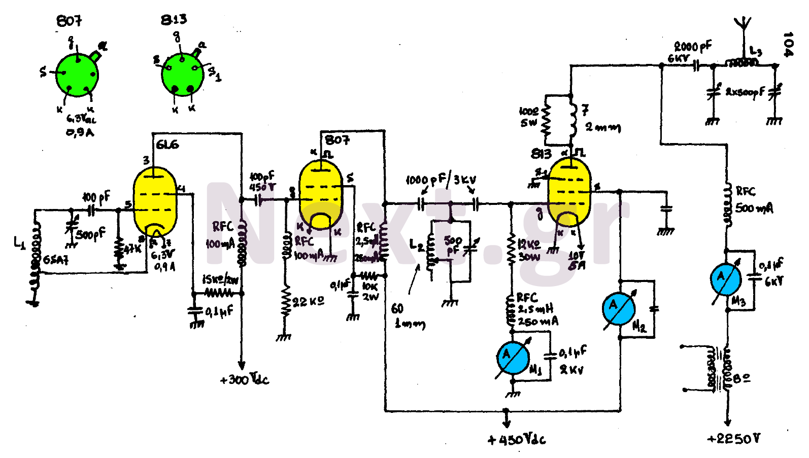
The circuit consists of three main stages and provides the antenna with a power output of 300 watts, contingent upon proper tuning. The first stage is an oscillator featuring an oscillating coil L1, which is commercially available as a...

The DPT Transmitter is a dual-powered voice transmitter designed to operate in two modes: a high-power mode for long-range transmission and a low-power mode for extended battery life. It functions at a low power level of 100 mW and...
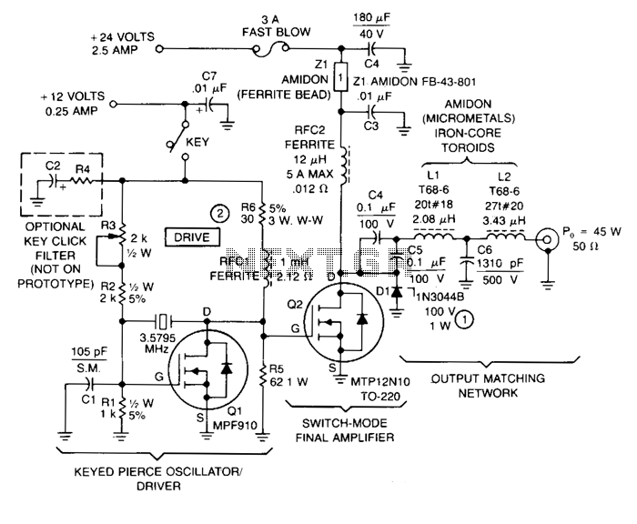
This transmitter comprises a keyed crystal oscillator/driver and a high-efficiency final amplifier, both utilizing a TMOS Power FET as the active component. The total cost of components is under $20, and no specialized construction skills or circuit boards are...
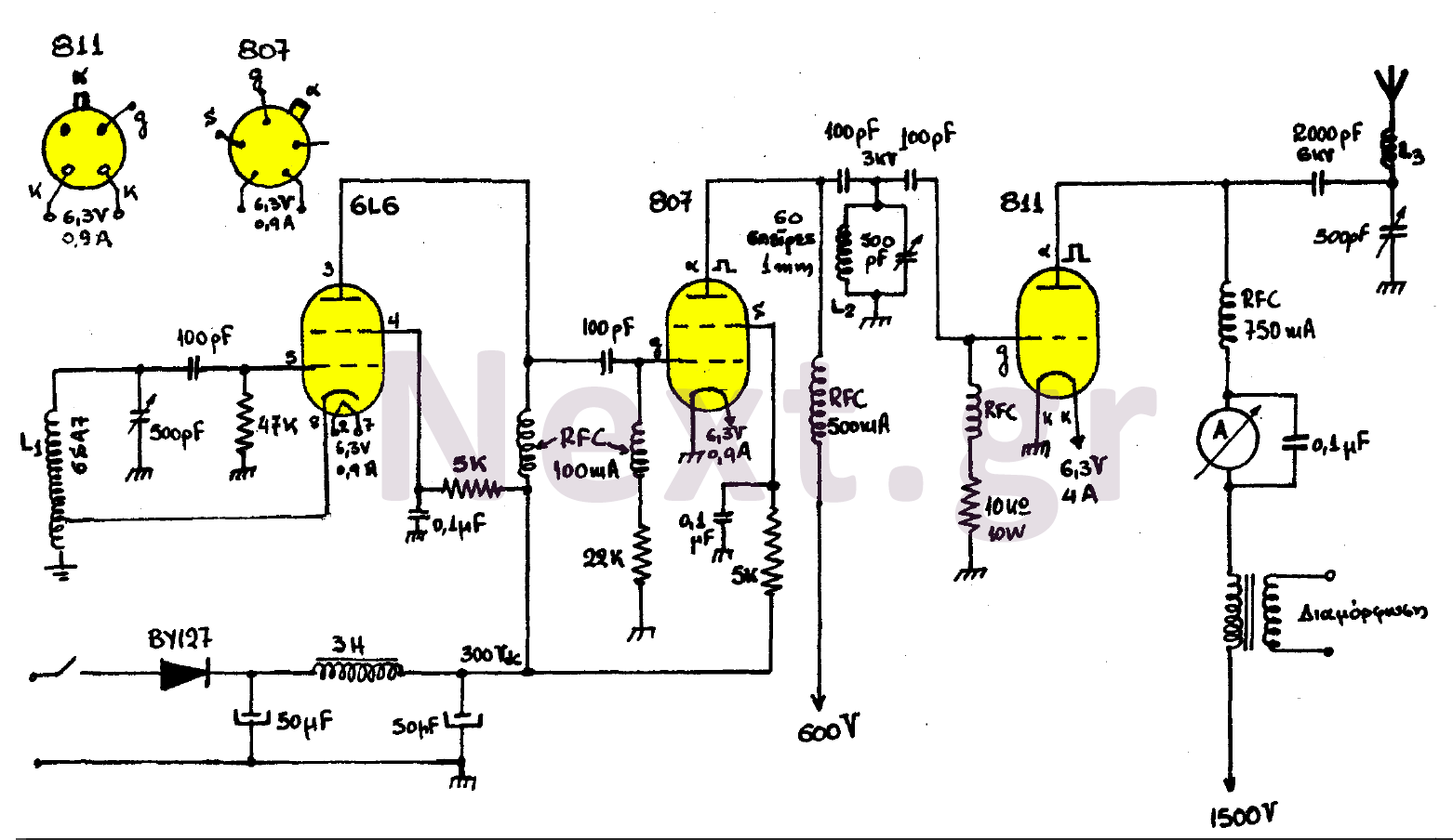
This transmitter consists of three stages: the oscillator stage utilizing a 6L6 tube, the amplifier isolator stage with an 807 tube, and the final stage of the transmitter featuring an 811 tube. The coil L1 is specified by the...
This timer was designed primarily to turn off a portable radio after a specific duration. This feature allows users to fall asleep on the beach or in a hammock, with the assurance that the radio will automatically shut off...