
ultrasonic transmitter circuit
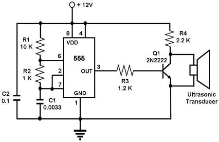
The circuit design begins with the 555 timer IC, which is a versatile component widely used for generating precise timing and oscillation. In the astable configuration, the 555 timer operates without any external triggering, continuously switching its output between high and low states. The frequency of oscillation is determined by the external resistor-capacitor (RC) network connected to the timer. The values of these resistors (R1 and R2) and the capacitor (C1) are calculated using the formula:
\[ f = \frac{1.44}{(R1 + 2R2) \times C1} \]
For a target frequency of 40 kHz, appropriate resistor and capacitor values must be selected. For example, if R1 is set to 1 kΩ and R2 to 10 kΩ, and C1 is chosen as 1 µF, the resulting frequency can be closely approximated to 40 kHz.
The output from the 555 timer is fed into the base of transistor Q1, which acts as a buffer and amplifier. This transistor can be chosen based on its ability to handle the required current and voltage levels for driving the ultrasonic transducer. Common choices include NPN transistors like the 2N3904 or the BC547. The amplified output from Q1 is sufficient to drive the ultrasonic transducer, which is capable of converting the electrical signal into mechanical vibrations at the desired frequency.
The ultrasonic transducer itself is a piezoelectric device that vibrates when an alternating voltage is applied. It is essential that the transducer is rated for operation at 40 kHz to ensure efficient sound wave generation. The emitted ultrasonic waves can then be used for various applications, including distance measurement and obstacle detection.
When used in conjunction with an ultrasonic receiver, the system can operate as a proximity sensor. The transducers must be positioned correctly to ensure that the receiver detects only the reflected sound waves from nearby objects. This setup minimizes interference from the direct transmitted signal, enhancing the accuracy of distance measurements and obstacle avoidance capabilities. Proper calibration and alignment of the transmitter and receiver are critical for optimal performance in robotic applications.The circuit uses a 555 timer IC configured as an astable multivibrator, i. e. , it generates a continuous signal of a set frequency as long as its reset pin (pin 4) is held high. Since the ultrasonic transducer used in this circuit is one designed to vibrate optimally at about 40 kHz, the resistor and capacitor values of the circuit were chosen such that the 555 will output a signal whose frequency is about 40 kHz. This 555 output is amplified by Q1, which drives the ultrasonic transducer. The transducer then vibrates at 40 Khz, generating ultrasonic sound waves of that frequency. If paired with a matching ultrasonic receiver, such a simple transmitter can be used as a proximity sensor, such as one that can help a robot avoid running into walls. If used in that manner, the transmitter and receiver transducers must be positioned such that the receiver will only receive echoes of the transmitted signal and not the transmitted signal itself.
🔗 External reference
Related Circuits
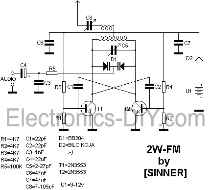
This 2 Watt FM transmitter is capable of providing a range of up to 10 kilometers under optimal weather conditions. For maximum range, a dipole antenna should be utilized. The transmitter can be tuned to frequencies between 88 and...
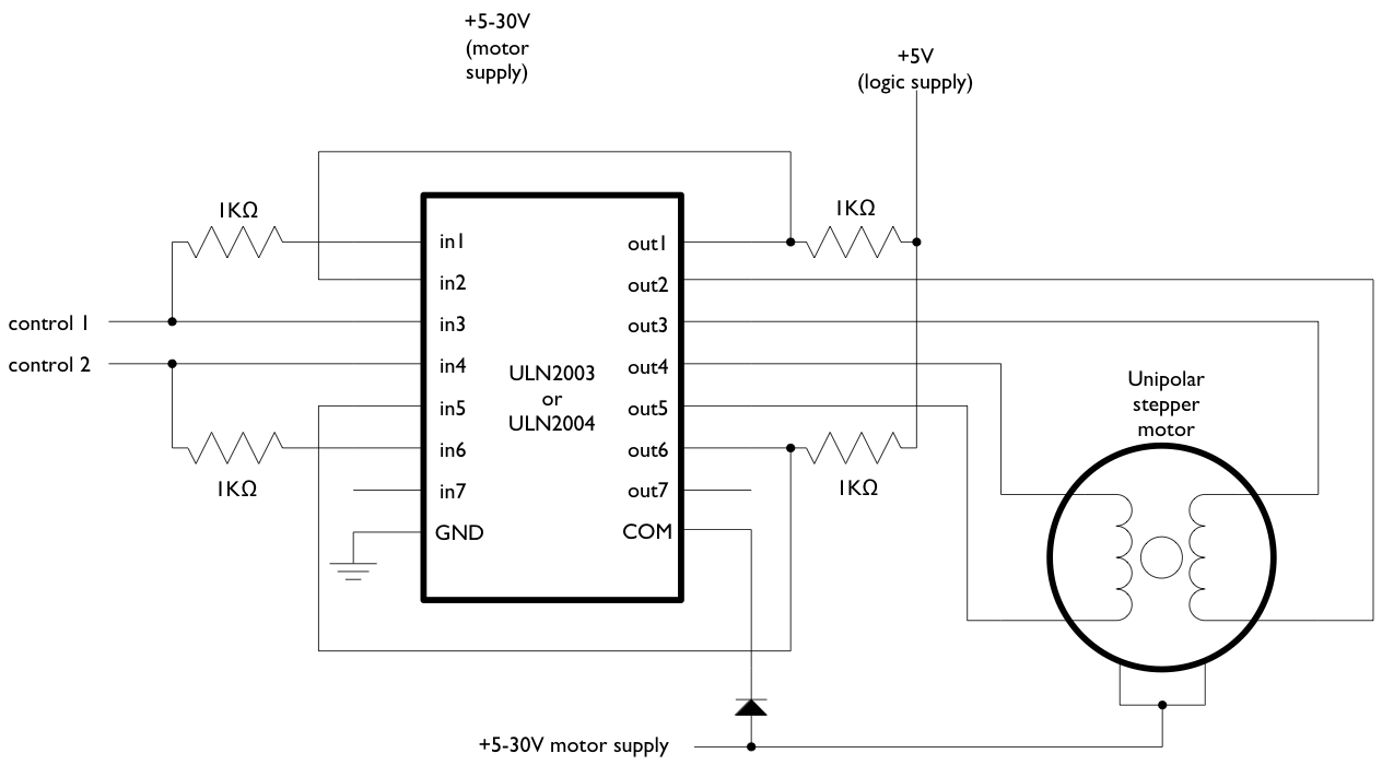
The text of the Arduino reference is licensed under a Creative Commons Attribution-ShareAlike 3.0 License. Code samples in the reference are released into the public domain. The Arduino platform is an open-source electronics prototyping environment that enables users to create...
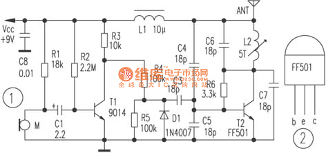
The circuit depicted utilizes a specialized launch tube T2 along with its associated components to create a high-frequency oscillator operating within the frequency range of 88 to 108 MHz. An electret microphone captures the audio signal, which is subsequently...
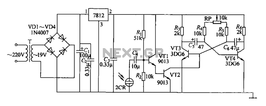
220V AC voltage is transformed by transformer T to 19V. After passing through a full-wave bridge rectifier and filter capacitor C, the voltage is regulated to DC using a 7812 voltage regulator. When the battery indicator light is illuminated,...
Most universal radio receivers have a very wide bandwidth that is not particularly suitable for radio amateurs. The better models with narrower bandwidth are almost a... Universal radio receivers are designed to operate over a broad frequency range, making them...
The 60 Hz frequency generator circuit is essential for creating inverters or hardware related to AC current voltage. This 60 Hz frequency generator is straightforward and highly accurate, producing a precision square wave output. The core of this generator...