
Metal detector circuit diagram 5
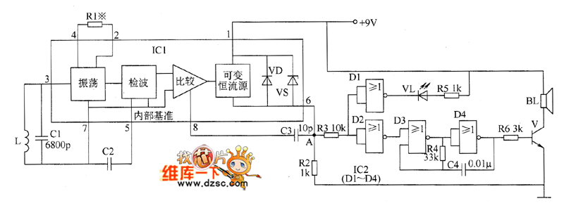
The metal detector circuit is designed to detect metallic objects by employing an oscillator to generate a frequency signal that varies in response to the presence of metal. The inductor (L) and capacitor (C1) form a resonant circuit that oscillates at a specific frequency. The sensor switch integrated circuit (IC1), specifically the TDA0161D, houses essential components such as the oscillator, detector, and comparator. This integrated circuit plays a crucial role in processing the signals and determining whether a metallic object is present.
Upon detection of metal, the output from IC1 triggers the sound-light alarm circuit, which is built around the CD4001 integrated circuit containing four NOR gates (IC2). The output from the detector is fed into these NOR gates, which can be configured to activate the alarm system. The sound-light alarm circuit includes a high-brightness light-emitting diode (VL) that visually indicates detection and a speaker (BL) that emits audible alerts.
The resistors (R1 to R6) are selected as 1/4W carbon film types, ensuring stability and reliability in the circuit. Capacitors (C1 to C4) are chosen as ceramic capacitors, known for their low losses and excellent frequency characteristics, which are vital for maintaining the performance of the oscillator. The choice of a 5mm high-brightness LED ensures that the visual alarm is easily noticeable, even in bright environments.
The use of an S9013 or C8050 silicon NPN transistor allows for effective switching capabilities within the circuit, facilitating the control of the alarm components based on the input signal from the sensor switch. Overall, the design of the metal detector circuit integrates these components in a cohesive manner to provide a reliable and efficient means of detecting metallic objects and alerting the user through both sound and light signals.The metal detector circuit consists of oscillator and sound-light alarm circuit, and the circuit is shown as the chart. Oscillator circuit consists of inductor L, capacitor C1, sensor switch integrated circuit IC1 (includes oscillator, detector and comparator circuit, etc.
) and the peripheral components. Sound-light alarm circuit consists of four NOR gate integrated circuit IC2 (Dl ~ D4) and the light-emitting diode VL, speaker BL and other components. R1 ~ R6 select 1/4W carbon film resistors. C1 ~ C4 select ceramic capacitors. VL selects 5mm high-brightness light-emitting diode. V uses S9013 or C8050 silicon NPN transistor. IC1 uses TDA0161D sensor switch integrated circuit; IC2 selects CD4001 four NOR gate integrated circuit.
🔗 External reference
Related Circuits
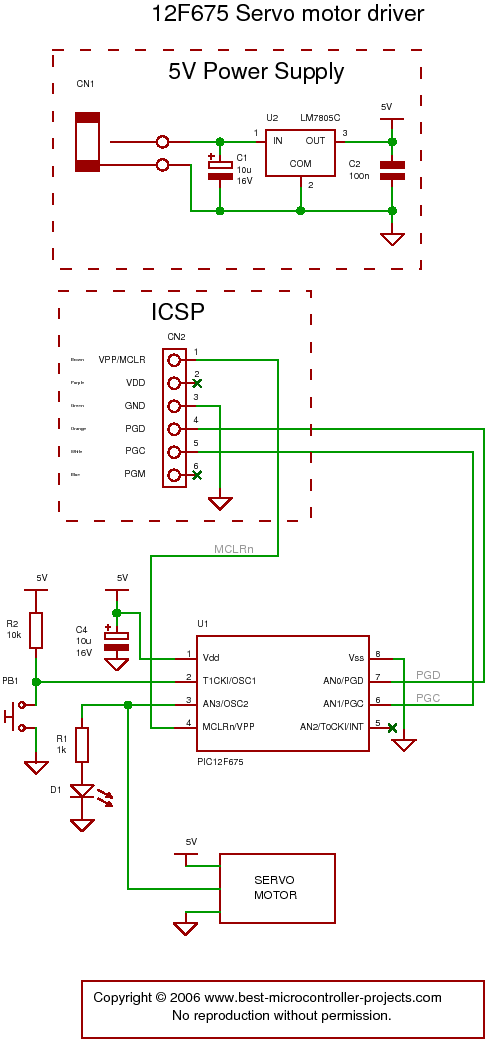
The following circuit illustrates a servo motor driver. This circuit is based on the 12F675 IC. Features include Timer 0 timing and a single control line. The servo motor driver circuit utilizing the 12F675 integrated circuit (IC) is designed to...
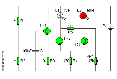
The circuit diagram of the Lie Detector consists of three transistors (TR1 to TR3), a capacitor (C1), two LEDs (L1 & L2), five resistors (R1 to R5), and a variable resistor (VR1). Suitable transistors include BC547, BC548, or BC549,...
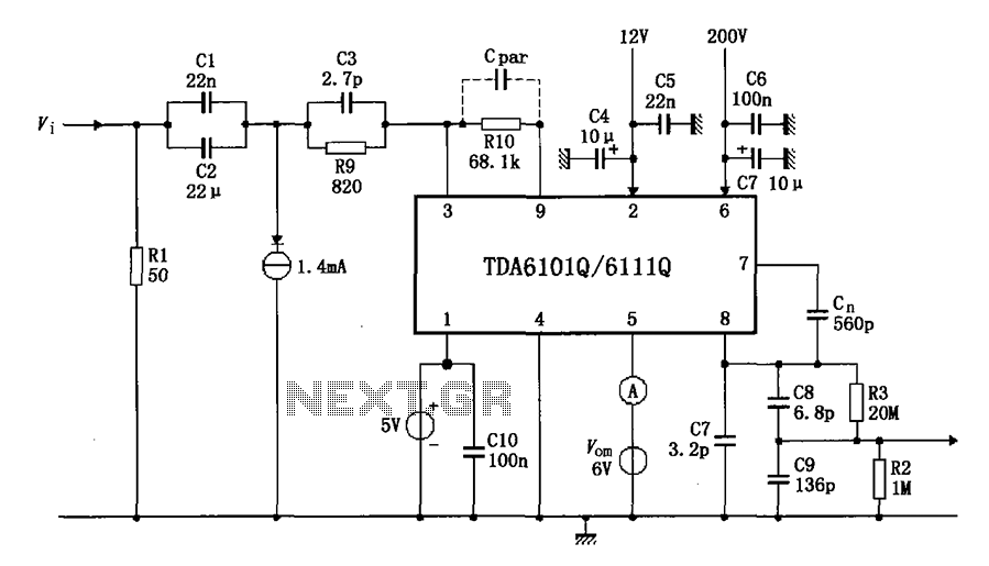
The test circuit features a feedback factor of 1/83 utilizing the DA6101Q/6111Q. The input signal is fed through a network comprising resistors R1 and R9, and capacitors C1, C2, and C3, entering the TDA6101Q, which includes three pins for...
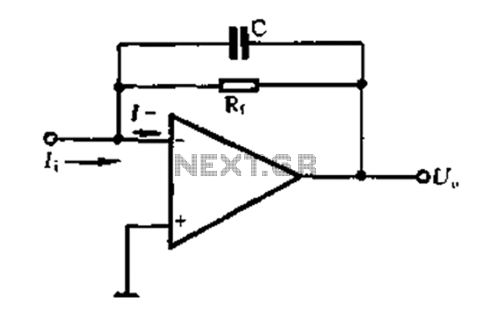
A current-voltage conversion circuit. A current-voltage conversion circuit is designed to transform an input current signal into a corresponding voltage signal. This type of circuit is fundamental in various applications, including sensor interfacing, signal conditioning, and analog-to-digital conversion processes. Typically,...
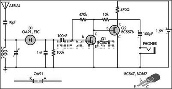
This circuit is an amplified crystal set. The inductor can be a standard AM radio ferrite rod antenna, while the tuning capacitor is a variable plastic dielectric gang designed for small AM radios. The aerial tuned circuit feeds diode...
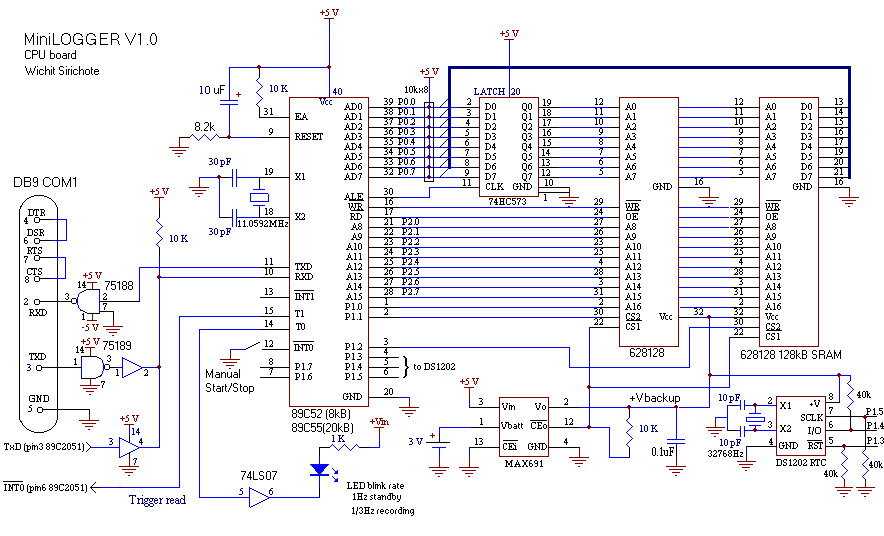
Build a personal data logger for recording analog signals. The MiniLOGGER provides 8-channel analog input (-99mV to +999mV), 1-channel pulse input, battery backup with 256kB SRAM, a Real-time Clock, and RS232C communication. Recording can be initiated or stopped using...