
Servo Motor Driver Circuit With 12F675 IC
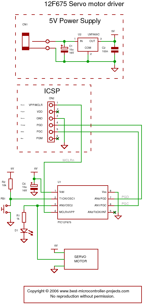
The servo motor driver circuit utilizing the 12F675 integrated circuit (IC) is designed to provide precise control over servo motors. The 12F675 is an 8-bit microcontroller from Microchip Technology, which is well-suited for applications requiring compact size and efficiency.
The circuit typically includes the following components: the 12F675 microcontroller, a power supply module, a servo motor, and necessary passive components such as resistors and capacitors for stability and signal conditioning. The core functionality of the circuit revolves around Timer 0, which is configured to generate timed pulses that correspond to the desired position of the servo motor.
The single control line mentioned in the description is responsible for receiving the pulse-width modulation (PWM) signals from the microcontroller. This control line directly influences the angle of the servo motor by varying the width of the pulses sent. A wider pulse will command the servo to move to a specific position, while a narrower pulse will adjust its position accordingly.
To ensure optimal performance, the circuit may include decoupling capacitors close to the power pins of the 12F675, which help to filter out noise and stabilize the power supply. Additionally, pull-up or pull-down resistors may be implemented on the control line to ensure a defined logic level when the line is not actively driven.
Overall, this servo motor driver circuit is an effective solution for applications that require precise motor control, and the use of the 12F675 microcontroller allows for flexibility in programming and integration into larger systems.The following circuit shows about servo motor driver. This circuit based on the 12F675 IC. Features: Timer 0 timing, single control line from .. 🔗 External reference
Related Circuits
The following circuit illustrates the SCR BRY35 used in a simple radio control circuit. Features include a straightforward and efficient receiver for operation. The SCR BRY35 is a silicon-controlled rectifier designed to facilitate the control of high-power loads through low-power...
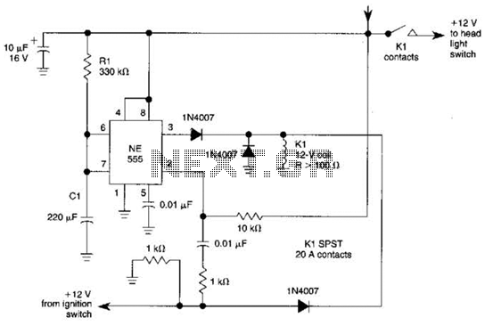
When the ignition switch is activated, relay K1 receives continuous power, allowing the headlights to be turned on. When the ignition is turned off, timer IC1 is activated, maintaining its power for a duration determined by resistor R1 and...
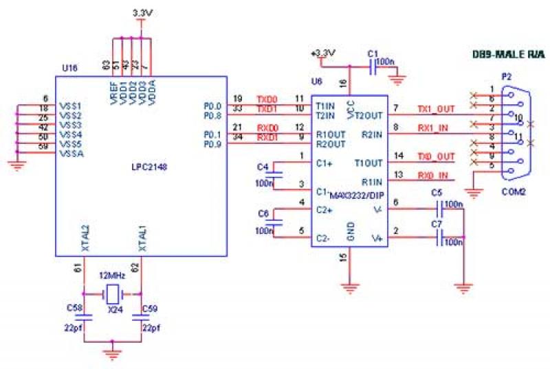
The interfacing of a Bluetooth module with the LPC2148 microcontroller is a straightforward process that enables the transmission of messages from the LPC2148 Primer Board to mobile devices via Bluetooth using UART0. Some delays may occur when sending a...
L1 is 0.112uH (this tunes to the middle of the FM band, 98 MHz, with VC1 at its centre value of 33pF). L1 is 5 turns of 22 swg enamelled copper wire close-wound on a 5mm (3/16") diameter former....
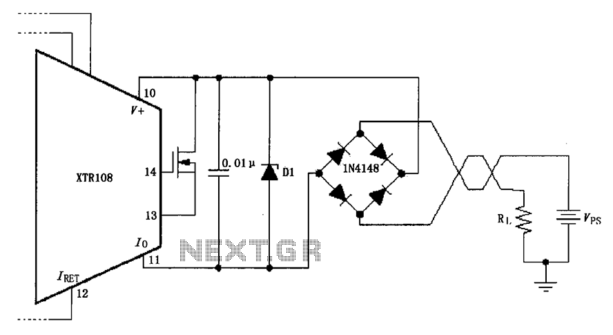
The circuit utilizes a Zener diode (D1) for overvoltage protection and a diode rectifier bridge for reverse voltage protection. The 1.4V drop across the diodes will result in a maximum voltage loss, meaning that the supply voltage (VPS) must...
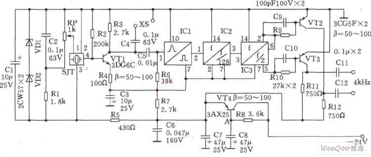
This circuit is a 1024 kHz temperature-compensated crystal oscillator. The circuit theory is illustrated. Due to the low output signal level of the circuit, a buffer using the following transistor VT1 is implemented for amplification. The base bias resistor...