
lie detector
The Lie Detector circuit integrates several components to achieve its functionality. The three transistors (TR1, TR2, and TR3) are critical for signal processing and comparison. TR1 serves as a buffer, ensuring that the voltage from the probe wire is transmitted effectively to TR2 without significant loss. The voltage divider formed by R1 and R2 is essential for establishing a reference voltage that is responsive to changes in skin resistance. The variable resistor (VR1) allows for fine-tuning the sensitivity of the circuit, enabling the user to calibrate the detector based on individual skin resistance characteristics.
The LEDs (L1 and L2) serve as visual indicators of the circuit's output, providing immediate feedback on the detected voltage levels. The use of a capacitor (C1) may be to filter out noise or stabilize the voltage levels in the circuit, ensuring reliable performance. The design of the circuit allows for a versatile application, not only for lie detection but also for various educational and practical experiments regarding conductivity and moisture levels in different materials.
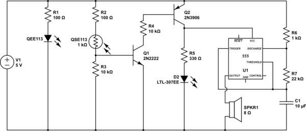
Overall, the Lie Detector circuit exemplifies a straightforward yet effective application of electronic components to create a device that can measure physiological responses to emotional states, providing insights into human behavior through its operation.The circuit diagram of the Lie Detector is shown above. It consists of three transistors (TR1 to TR3), a capacitor (C1), two lights or LED`s (L1 & L2), five resistors (R1 to R5), and a variable resistor (VR1). Suitable transistors to use are BC547, BC548 or BC549, or any other small NPN transistor. The Lie Detector circuit works based on the fact that a person`s skin resistance changes when they sweat (sweating because they`re lying). Dry skin has a resistance of about 1 million ohms, whereas the resistance of moist skin is reduced by a factor of ten or more. Resistors R1 and R2 form a voltage divider. They have resistance`s of 1 000 000 ohms (1 meg ohms) and, because their values are equal, the voltage at the upper probe wire is half the battery voltage (about 4.
5 volts). A person holding the lie detector probe wires will change the voltage at the upper probe wire depending on their skin resistance. The skin resistance is in parallel with R2 and, because it is likely to be similar to or smaller than R2, the voltage at the probe wire will fall as skin resistance falls.
TR1 and R3 form a buffer circuit (called an emitter-follower). The voltage at the emitter of TR1 follows the voltage at the probe wire and is now able to drive transistor TR2. Transistors TR1 and TR2 act as a voltage comparator. If the voltage at the base of TR2 is higher than at the base of TR3 then the green LED (L1) will come on.
If the reverse is true then the red LED (L2) will light. To test the Lie Detector hold the ends of the probe wires (the conductors). Adjust VR1 until the green LED is just on and the red LED is just off. This is the point at which the voltage at the base of TR2 is just greater than at the base of TR3. Now use moist fingers to hold the probes. This lowers the skin resistance and causes the voltage at the base of TR2 to fall. The voltage at the base of TR3 is now greater and the red LED comes on. Touch the two probe wires against the palm of your (dry) hand, such that the metal ends are a couple of centimeters apart (the metal ends must not touch each other). Adjust the tuning control (VR1) until the red light (FALSE) just goes out. The Lie Detector is now tuned for your skin. If you lick your palm and touch the wires against it again, the red light should come on brightly. You should now understand how to use the Lie Detector to detect a real lie. Touch the two probe wires against the palm of the subject`s hand and adjust the tuning control as before until the red light just goes out.
When the subject tells a lie, and begins to sweat, the red light will get brighter. It must be emphasized that the Lie Detector won`t detect every lie, as it is really only a sweat detector. It only detects lies that have consequences to being told, lies that cause the subject to sweat (with fear).
Pretend or `joke` lies won`t have any effect. Use lie detector to test the conductivity of the human body. Get a group of people to hold hands in a circle with the two probes of the lie detector as part of the circle. See how many bodies the current will flow through to make the red LED light. Testing the conductivity of objects. For example, metals, plastics, wood, hair, the lead of a pencil. If a material is conductive then touching the probe wires against it will make the red LED light. Determining whether a houseplant needs watering. Touch the probe wires against the soil. If the green LED stays on, the plant needs watering. If the red LED comes on, the soil is sufficiently moist. Determining whether a cake is cooked. Press the probe wires into the surface of the cake. If the red LED comes on then the cake is still moist and needs further cooking 🔗 External reference
Related Circuits
This circuit detects when a tube is empty and pulses a piezo buzzer at 5-second intervals. It is currently operational with a 5V supply on a breadboard but needs to be adapted for a 12V supply from a wall...

This simple circuit is designed to detect RF radiation leakage from transmitters, faulty connections, broken cables, or equipment with inadequate RF shielding. It is specifically tailored for the 2-meter amateur radio band (144-146 MHz in Europe). The device features...
This circuit is activated by an increase in capacitance between a sensing electrode and the ground side of the line. The sensitivity can be adjusted to trigger when a human body is within inches of the insulated plate used...

The basic operation of the monitor connected to the circuit is to detect objects (obstacles) at distances ranging from a few millimeters to several centimeters. This type of circuit is utilized in various industries and hospitals. The position sensor...

A reflector isolator detects the presence of an object by bouncing light off of it. This technique is useful in circuits that detect when an object is close enough to the sensor. A reflector isolator is a type of optical...
This circuit utilizes a synchronous demodulator to extract a 1 kHz signal from noise and measures its amplitude, with the 1 kHz signal providing a resolution of approximately 60 microvolts per count. The measurements are transmitted via an RS-232...