
Motion Sensor Light Circuit
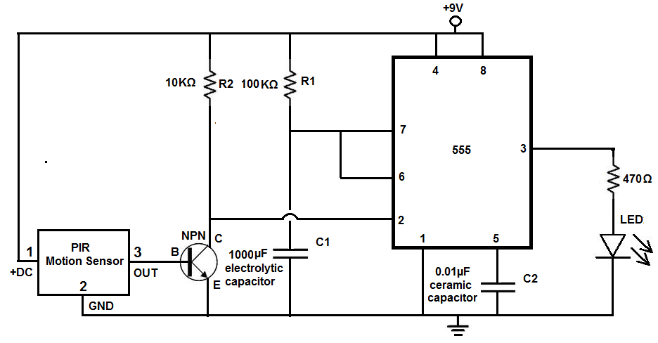
Power for the PIR motion sensor is supplied through pin 1, requiring 5V-9V DC, typically provided by a 6V power source or four AA batteries in series. The output pin (pin 3) of the PIR module sends a high signal (3V) when motion is detected and a low signal when no motion is present. This output connects to the base of an NPN transistor, which activates an LED when the PIR sensor detects motion. The connection to an Arduino allows for further control, where pin 1 connects to +9V DC, pin 3 connects to ground, and pin 2 connects to digital pin D3 on the Arduino. An LED is connected to digital pin D13, which has internal resistance, eliminating the need for an external resistor.
When the Arduino is powered and programmed, it will light the LED when motion is detected. The code specifies pin assignments and detects whether the PIR sensor output is HIGH or LOW. If HIGH, the LED turns on for 30 seconds, but this duration can be adjusted by modifying the delay() function in the code. For example, changing the delay to 60000ms or 120000ms adjusts the LED duration to one or two minutes, respectively. This circuit activates regardless of ambient light conditions. To create a version that only activates in the dark, a photoresistor can be added in a future project.
The circuit design utilizes the PIR motion sensor for detecting movement through infrared radiation. The sensor's functionality is based on detecting the infrared waves emitted by human bodies, which allows it to recognize when individuals are present within its detection range. The motion sensor's sensitivity can be fine-tuned through empirical testing, ensuring optimal placement for desired coverage.
The power supply is critical for the operation of the PIR sensor. By providing a stable voltage of 6V, either from a regulated power supply or battery source, consistent performance is ensured. The output pin of the PIR sensor interfaces directly with an NPN transistor, which serves as a switch to control the LED. When the PIR sensor detects motion, it sends a high signal to the transistor, allowing current to flow and illuminating the LED.
The Arduino microcontroller enhances the circuit's capabilities by allowing for programmable control over the LED's operation. By writing and uploading a specific code to the Arduino, the behavior of the LED can be customized based on detected motion. This flexibility allows users to adjust the timing and functionality of the motion sensor light, adapting it to various applications as needed.
In summary, the motion sensor light circuit effectively combines a PIR motion sensor, an NPN transistor, an LED, and an Arduino microcontroller to create a responsive lighting system that activates upon detecting movement. This versatile design can be tailored to meet specific requirements, such as duration of illumination and sensitivity, making it suitable for a wide range of applications in both residential and commercial environments.Many people place motion detectors in their backyards or even in their houses so that when they walk through that area, the lights will automatically turn on. Thus, motion sensor lights are very popular and being increased in use. Businesses use them all the time such as for bathrooms, when a person walks in, the lights turn on. Or many times they are used in grocery stores for when you pass through an aisle or open up a refrigerator door in the freezer aisles. The applications are numerous. In this circuit, we will create a motion sensor light circuit that will stay on for 30 seconds minutes when motion is detected.
This is just for demonstration purposes. Depending on what you use the circuit determines how long you may want the lights to stay on for. For a refrigerator application such as in a supermarket when the fridge door opens, 30 seconds would be adequate. Usually people don`t stay in the fridge that long. If you`re using it for a bathroom, a longer time period may be necessary such as 2-3 minutes. If the person is still in the bathroom and moving, the sensor will turn right back. The main electronic component we will use that allows us to pick up this detection is the PIR motion sensor.
The PIR motion sensor is a sensor which detects movement through picking up infrared waves. Being that a person emits infrared waves, the detector is able to detect these waves and react, according to the how the circuit is designed to react. The sensor can also pick up the movement of inanimate objects as well, such a rolling ball, because as those objects move, friction acts on them, generating heat.
This heat emits infrared radiation, which the PIR sensors may be able to detect if great enough. The PIR motion sensor is, again, a sensor which can detect movement through picking up infrared radiation. Being that people naturally give off radiation, because of our generated body heat, the motion can easily detect people walking and moving through a vicinity within the sensor`s range.
The motion sensor has a sensitivity range up to 20 feet (6 meters) and a 110G‚ ° x 70G‚ ° detection range, making it a wide lens detection sensor. This means it can measure 110G‚ ° vertically (from top to bottom) and 70G‚ ° horizontally (from left to right).
The best way to check its sensitivity is when the circuit is built, try moving around through all of its angles. See at which angles it can detect your movement and at which angles it is not able to detect your movement, meaning your out of its angle scope.
A lot of it is trial and error and experimenting. Once you know where it can and cannot detect, you can place it in an optimal place where it can detect in areas where you want it to. Pin 1 is the pin which receives the positive DC voltage. The PIR motion sensor needs between 5V-9VDC of power for operation. In our case, we will use about 6V of power. This can be obtained from switching a DC power supply to 6V or using 4 `AA` batteries connected in series.
We will then feed this voltage into pin 1 of the PIR module. Pin 3 is the Output pin of the PIR module. This is where the output of the PIR will leave from. When motion is detected by the PIR, its output will go high to 3V. When no motion is detected, its output is low and it gives off practically no voltage. The output pin will connect to the base of an NPN transistor. When no motion is detected, the output is LOW and no current flows from the output of the sensor. Therefore, the transistor does not get turned on. When motion is detected, the output is HIGH and current flows from the output of the sensor and turns on the transistor. The turned-on transistor then turns on the LED that is attached to output. This is the motion sensor light. We will place the output of the PIR sensor into a digital pin of the arduino. The arduino will then be able to tell if the PIR sensor is outputting a LOW or HIGH signal. If it is outputting a LOW signal, this means the PIR sensor has not detected any motion. The LED we will connect to another digital pin, in this case, will not light. If the sensor is outputting a HIGH signal, this means the PIR sensor has detected motion, and the LED connected to the arduino, we will program to light in this case.
We connect pin 1 of the PIR sensor to +9VDC and we connect pin 3 of the sensor to ground. This gives the PIR sensor the power it needs to operate. We connect pin 2, the output pin of the PIR sensor, to digital pin D3 of the arduino. This pin will detect whether the PIR sensor is outputting current (motion detected) or not (no motion detected). We connect to an LED to digital pin D13. We do not need to connect an external current-limiting resistor to this LED, because digital pin D13 of the arduino already has internal built-in resistance.
So we do not need to worry about excess current burning out the LED. Therefore, we can just hook the anode of the LED directly to D13 and the cathode to GND of the arduino. After we connect the USB from the arduino to the computer, we are ready to write the code that the arduino board will need uploaded to it so that it knows to light the LED when motion is detected.
The first block of code chooses the pin for the LED, which is pin 13. The second line chooses the pin for the input pin, which represents the PIR sensor, pin 2. The fourth block of code determines whether the sensor pin is HIGH or LOW. If it is HIGH, then the motion sensor has detected motion. If it is low, the sensor has not detected any motion. If the value is HIGH, it turns the LED on, signaling that motion has, in fact, been detected. The LED stays on for 30, 000ms, which is equal to 30 seconds. After this period of 30 seconds has elapsed, the LED then turns LOW. Again, you can modify this code so that the LED stays on for 1 minute after motion has been detected. You can modify it so that it stays on for 2 minutes or 3 minutes. All this can be done by changing the value given to the delay() function. 1 minute would be 60000ms. 2 minutes would be 120000ms. Customize the code to suit your circuit`s needs. This is a motion sensor light circuit that turns on when there is any motion, whether in the light or in the dark.
Many times, it is only wanted for motion sensor lights to come on when it is dark. If it already bright, then many times we wouldn`t need the light to turn on. To create a motion sensor light that turns on only when it`s dark, we will need to modify the above circuit so that we add a photoresistor so that it only turns on when it gets dark. We will do this in another project. But for now, just realize that the above motion sensor light circuit turns on when there is any motion detected, whether it is bright or dark in the surroundings.
🔗 External reference
Related Circuits
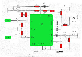
The amplifier circuit utilizes the STK integrated circuit, similar to a previous design. This circuit features two inputs and two outputs, commonly known as a stereo amplifier. It is a power amplifier rated at 2 x 18 Watts with...
The circuit this month is a simple 8 light chaser built around a PIC. This will demonstrate how easy it is to program a PIC and to utilize it in a circuit. The circuit works as follows. When power...

The finish line circuit below detects the first of three cars to cross the line and illuminates a 25 watt 120 VAC lamp indicating the winning lane. Three photo transistors are used which can be embedded into the track...

This circuit simulates the flashing strobe lights of British police cars by alternating the lights. The IC1a functions as a square wave oscillator with an adjustable frequency controlled by VR1 to achieve the desired effect. The circuit utilizes an...

This electronic lighting dimmer circuit is designed to control the brightness of incandescent lamps, but it is not suitable for fluorescent lamps. It operates with both 110V and 220V AC power sources. The circuit is connected in series with...
The circuit below illustrates generating a single positive pulse which is delayed relative to the trigger input time. The circuit is similar to the one above but employs two stages so that both the pulse width and delay can...