
PIC Light Chaser with PIC16C84
The circuit described employs a PIC16F84 microcontroller to create an 8-light chaser effect using light-emitting diodes (LEDs). The primary function of the circuit is to sequentially illuminate each LED with a defined delay, creating a visually appealing "chasing" light pattern. Upon powering the circuit, the microcontroller initializes and executes the preloaded instructions.
The microcontroller operates at a frequency of 75 kHz, allowing each LED to remain illuminated for approximately half a second before the next LED is activated. The program is structured in assembly language, with the first part consisting of comments that clarify the purpose and functionality of each code segment. The comments are prefixed with a semicolon, indicating that they are not processed by the assembler.
The program begins with configuration settings that specify the use of the PIC16F84 architecture, the inclusion of predefined constants from the P16F84.inc file, and the configuration of essential operational parameters such as the RC oscillator and watchdog timer settings. The TRIS register is manipulated to define the direction of the port pins, setting them as outputs.
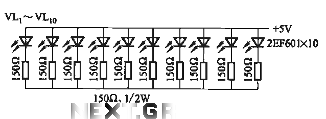
The main operational loop of the program employs the `rlf` (Rotate Left f) instruction to shift the output state of PORTB, effectively cycling through the binary representations that correspond to the individual LEDs. The LEDs are connected to PORTB pins, with the first LED turning on when the binary state is `00000001`, and subsequent LEDs lighting up as the binary value is rotated left.
To manage the timing between LED activations, the program incorporates a delay loop that counts down from a predetermined value stored in memory locations designated as "J" and "K". The `decfsz` instruction is utilized to decrement the counter and create the necessary delay, ensuring that the LED transitions are visually discernible.
The program concludes with a jump back to the main loop, allowing the sequence to repeat indefinitely until power is removed. The assembler recognizes the `end` directive as an indication that the program has concluded, facilitating the compilation process.
To program the PIC with this assembly code, a suitable development environment such as MPLAB is employed, along with a programming tool like No Parts Programmer (NOPPP). This setup allows for the conversion of the written instructions into a binary format that can be uploaded to the microcontroller. Following successful programming, modifications to the code can be made to create different LED lighting patterns, showcasing the flexibility of using a PIC microcontroller for such applications.The circuit this month is a simple 8 light chaser built around a PIC. This will demonstrate how easy it is to program a PIC and to utilize it in a circuit. The circuit works as follows. When power is supplied to the circuit the PIC resets and starts to process instructions that are programmed into it. The program will turn on each LED in sequence with a small delay between each one. It will continue to do this until power is removed. The nice feature with this circuit is that you can program it to perform many complex lighting sequences.
Normally you would have to rebuild a hardware based circuit to change the light sequence. With a PIC all you need to do is reprogram it and plug it back into the circuit. I am assuming that you will be using an IC socket. The circuit is show below and then I will discuss the program that is programmed into the PIC. The program is listed below: ;File DEMO.ASM ;Assembly code for PIC16F84 micro controller ;Blinks LED's on the outputs in a rotating pattern. ;With 75khz osc, each LED stays on half a second. ;CPU configuration ; (its a 16F84,RC Oscillator, watchdog timer off, power-up timer on) processor 16f84 include
J equ H'1F' ;J=Address hex 1F K equ H'1E' ;K=Address hex 1E ;Program org 0 ;start at address 0 ;Set port B as output and initialize it movlw B'00000000' ;w : =00000000 binary tris PORTB ;port B ctrl register := w movlw B'00000001' ;w := 00000001 binary movwf PORTB ;port B itself := w ;Rotate the bits of port B leftward mloop: rlf PORTB,f ;Waste some time by executing nested loops. movlw D'50' ;w := 50 decimal movwf J ;J :=w jloop: movwf K ;K :=w kloop: decfsz J,f ;J = J -1, skip next if zero goto kloop decsz J,f ;J = J - 1, skip next if zero goto jloop ;Do it all again goto mloop end The program works as follows.
The first few lines in the program are what is called comment lines. Comment lines assist us in documenting what each part of the programs function is. If a program is commented well, then it will be easier later own to understand why the program was written the way it was. Any line that begins with a semicolon is a comment line and will be ignored when the assembler is run.
The assembler is another program that will convert these written instructions and convert them to binary data to be programmed into the PIC. The first true commands that the PIC will process is the processor, include and _config. These instructions tells the assembler that it is using 16F84 instructions. The second instruction says to include a set of predefined constants in a file called P16F84.inc. Finally, the third instruction sets various configuration bits in the PIC to turn on the RC Oscillator, turn off the watch dog timer and turn on the automatic power up reset timer.
That way the PIC will reboot every time power is applied. The two equ instructions reserve memory space in the PIC's RAM for two variables, which is being called "J" and "K". The locations are in Hex 1E and 1F. Theses locations will be used to store counters to keep track of how many times a loop has been repeated.
The org instruction tells the assembler that the program starts at location 0. in the program memory and that the actual program is next. The first real PIC instruction is a movlw instruction that clears the working register called W. That number is then copied into the TRIS control register for Port B, setting pins 6 - 13 to outputs pins instead of input pins. Next the program puts binary 00000001 into the W register and copies it to Port B. That lights the LED connected to pin 6. But before you have time to actually see the LED come on, the program executes an rlf instruction that rotates the contents of Port B to the left , changing the data to 00000010.
That will light the LED on pin 7 instead. Repeating that instruction will give 00000100, and then 000010000 and so on, making the LED's flash in a marching pattern. In between rotations, the program needs to wait about a half second so that action isn't to fast to see.
That is the purpose of the delay loop. It stores the decimal number 50 in memory locations "J" and "K" using decfsz instruction to count down from 50 to 0. The decfsz instruction means " Decrement and skip next instruction if zero. The last instruction in the program is mloop which sends the program back to the beginning. The end instruction is not a CPU instruction. Instead it tells the assembler that the program is over. To compile the program for the PIC we will be using a program that can be downloaded directly from the Microchip Web site.
The program is called MPLAB. It is a developmental program for compiling and testing PIC programs. It will run under Microsoft Windows. The second piece of software that will be needed is the No Parts Programmer (NOPPP) that also works under Microsoft Windows. The use of the program is straight forward. You will load an object file that was created by MPLAB and program it into the PIC. After successfully programming the PIC and testing the circuit, try to modify the program to light the LEDS in a different pattern and then reprogram the PIC and test it.
🔗 External reference
Related Circuits

This circuit is a real core of the dimmer system. This circuit generates a ramp 100 Hz signal which is synchronized to the incoming mains voltage. The ramp signal which is generated will start from 10V and go linearly...
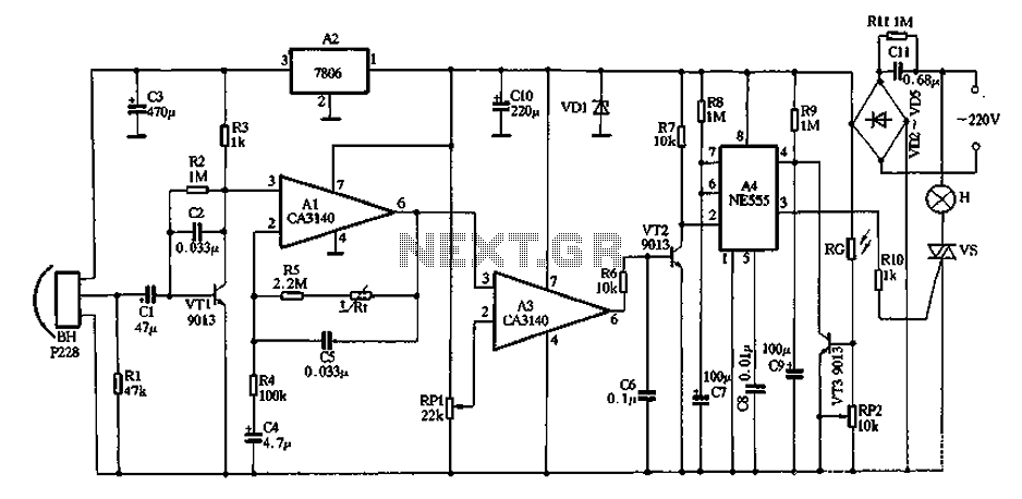
The core device is a circuit pyroelectric infrared sensor (BH). When it detects infrared radiation from a body, the sensor element responds to changes in temperature. As a thermoelectric element, its self-ferroelectric polarization value changes, causing a discharge of...
The circuit utilizes a 555 timer configured as a multivibrator, where the oscillation frequency is determined by resistors R1, R2, and capacitor C1. The frequency formula is given by fo = 1.443 / ((R1 + R2) * C1). The...
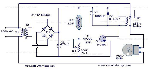
Watch the video below to gain a better understanding of how a light-emitting diode (LED) functions. An LED is recognized as one of the most effective optoelectronic devices available. This device emits a relatively narrow bandwidth of visible or...
Introduction and disclaimer for individuals interested in a fading dome light (also referred to as courtesy light or theatre lighting) without incurring high costs. A fading dome light circuit is designed to create a gradual illumination effect, enhancing the aesthetic...
This scanner uses a DDS circuit to scan through the frequency band. Since a DDS is used to set the desired frequency, this receiver can jump from one frequency to another within microseconds, making it very fast. The receiver...