
Police Car Lights with LEDs
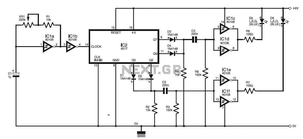
The circuit utilizes an integrated circuit (IC1a), which is typically a 555 timer or similar, configured in astable mode to generate a continuous square wave output. The frequency of this square wave can be adjusted using a variable resistor (VR1), allowing for customization of the flashing rate to closely mimic the distinct pattern of police car lights.
The output from IC1a is fed into a driver stage, which may consist of transistors or MOSFETs, to amplify the signal and drive the high-power LED strobe lights. These LEDs are arranged in a manner that reflects the traditional layout of police lights, often in a dual-color configuration (e.g., red and blue) to enhance visibility and realism.
The circuit may also include additional components such as resistors to limit current to the LEDs, capacitors for smoothing and stability, and possibly diodes for protection against reverse polarity. A power supply circuit is essential to provide the necessary voltage and current levels for the operation of the IC and LED lights.
In summary, this circuit effectively replicates the visual effect of police car lights through the use of a square wave oscillator, adjustable frequency control, and a suitable driver stage to illuminate high-power LEDs, making it an excellent tool for educational purposes or for use in model displays.This circuit is used to simulate the police car lights by alternating flashing strobes seen on British police cars. The IC1a forms a square wave oscillator having adjustable frequency with VR1 to give the best effect.
This square wave is bu.. 🔗 External reference
Related Circuits
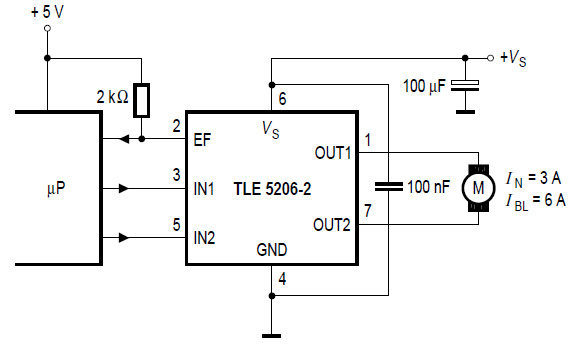
Stepper motor control circuit diagram using TLE5206 for remote control car. The stepper motor control circuit is designed to manage the operation of a stepper motor, specifically utilizing the TLE5206 integrated circuit. This circuit is particularly suitable for applications in...
To enable the MonomeSerial software to recognize the monome clone, it is necessary to modify the Arduino's EEPROM serial number to match that of a genuine monome. Following Melka's updated instructions from the Bricktable blog is recommended. The D2XX...
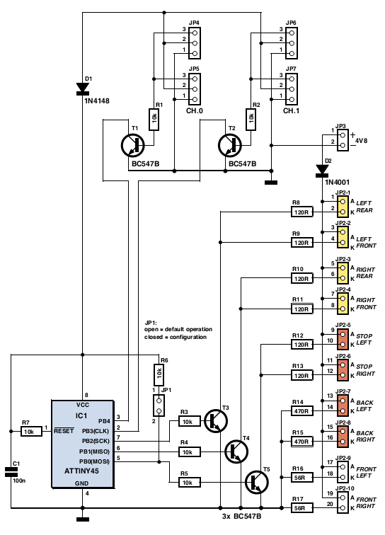
The author gifted a radio-controlled (RC) model car to his partner. She enjoyed it but suggested that adding realistic lights would enhance the experience. Consequently, the author returned to his workshop, utilized his soldering iron, and began outfitting the...
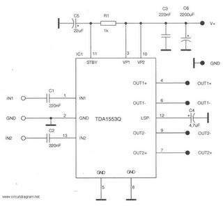
This is a 22-watt car stereo audio amplifier. The circuit is based on a single IC TDA1553 with a few peripheral components. This IC is designed for car audio applications. The TDA1553CQ integrates two 22-watt amplifiers with differential input...

The SD card can communicate using three different transfer modes: 1-bit SD mode, 4-bit SD mode, and SPI mode. According to Wikipedia, all cards must support all three modes, except for micro SD cards where the SPI mode is...
This circuit assists in parking a car near a garage wall by providing distance alerts. LED D7 illuminates when the bumper-wall distance is approximately 20 cm. When the distance decreases to about 10 cm, both D7 and D6 illuminate,...
Warning: include(partials/cookie-banner.php): Failed to open stream: Permission denied in /var/www/html/nextgr/view-circuit.php on line 713
Warning: include(): Failed opening 'partials/cookie-banner.php' for inclusion (include_path='.:/usr/share/php') in /var/www/html/nextgr/view-circuit.php on line 713