
Delaying Pulse from 555 circuit
The described circuit utilizes two 555 timer ICs configured in monostable mode to generate a delayed single positive pulse. The first 555 timer (Timer 1) is triggered by a button press, which causes its output to transition to a high state, close to the supply voltage. The timing for this high output is determined by an external resistor-capacitor (RC) network connected to Timer 1. The time constant of this RC network is designed to provide a delay of approximately 1 second, allowing the output to remain high for this duration.
While Timer 1's output is high, the second 555 timer (Timer 2) remains inactive because it is configured to trigger on a falling edge at its input pin (pin 2). The output of Timer 2 remains low during the delay period since the input voltage does not drop until Timer 1's output returns to low after the delay period elapses. This behavior ensures that the relay connected to Timer 2 remains de-energized until the appropriate timing sequence has completed.
Upon the expiration of the delay period, Timer 1's output transitions back to low, generating a falling edge at Timer 2's input. This falling edge triggers Timer 2, initiating its output cycle, which also lasts for about 1 second. During this time, the output of Timer 2 goes high, energizing the relay and allowing it to perform its intended function.
This configuration allows for independent control of both the delay and the pulse width, making the circuit versatile for various applications. The circuit can also be implemented using a dual 555 timer IC, such as the 556, which integrates both timers into a single package, though attention must be paid to the different pin configurations. The overall design is suitable for applications requiring precise timing control, such as in automation systems or timing circuits in various electronic devices.The circuit below illustrates generating a single positive pulse which is delayed relative to the trigger input time. The circuit is similar to the one above but employs two stages so that both the pulse width and delay can be controlled.
When the button is depressed, the output of the first stage will move up and remain near the supply voltage until the delay time has elapsed, which in this case is about 1 second. The second 555 stage will not respond to the rising voltage since it requires a negative, falling voltage at pin 2, and so the second stage output remains low and the relay remains de-energized.
At the end of the delay time, the output of the first stage returns to a low level, and the falling voltage causes the second stage to begin it's output cycle which is also about 1 second as shown. This same circuit can be built using the dual 555 timer which is a 556, however the pin numbers will be different.
🔗 External reference
Related Circuits
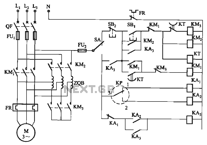
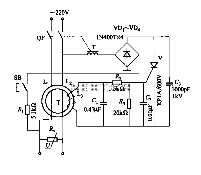
The circuit utilizes a motor auto-voltage transformer for starting. The motor auto-voltage transformer start circuit is designed to provide a controlled method for initiating the operation of an electric motor. This type of circuit is particularly beneficial in applications where...
The circuit presented is designed to prevent burning one's tongue by monitoring the temperature of coffee. It consists of a voltage regulator, a temperature-to-voltage converter, a comparator, and two LEDs. In general, the circuit operates as follows: if the...
A second RM output and a sync input have been added to the 555 timer circuit. The sync input is derived from one of Rene Schmitz's voltage-controlled oscillators (VCOs). There are two transistors in the PCB images that lack...
One of the simplest methods of metal detection is through a beat frequency oscillator. The circuit consists of two balanced oscillators: one provides a reference signal, while the other acts as the detector element. The frequency of the reference...
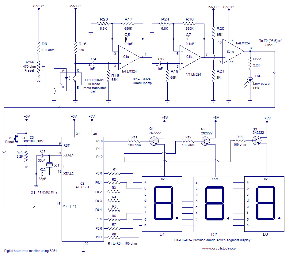
Heart rate monitor using an 8051 microcontroller. It measures the heart rate from the fingertip using an IR diode and phototransistor pair (Photoplethysmography). The AT89S51 microcontroller is utilized in this application. The heart rate monitor circuit operates based on the...
DBS-20 type leakage protection circuit The DBS-20 type leakage protection circuit is designed to detect and prevent electrical leakage, thereby enhancing safety in electrical installations. This circuit operates by monitoring the current flowing through the live and neutral conductors. When...
Warning: include(partials/cookie-banner.php): Failed to open stream: Permission denied in /var/www/html/nextgr/view-circuit.php on line 713
Warning: include(): Failed opening 'partials/cookie-banner.php' for inclusion (include_path='.:/usr/share/php') in /var/www/html/nextgr/view-circuit.php on line 713