Motorized Video Camera Mount
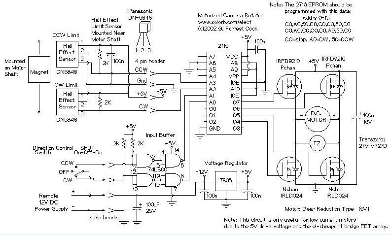
The camera rotator circuit utilizes a 2716 EPROM to store a logic value table that governs the motor driver (H-bridge) circuit. The schematic illustrates the EPROM data. By employing the EPROM, a significant number of discrete gates are eliminated. The logic table is structured to enable the motor to rotate clockwise until the clockwise limit sensor is triggered. A similar process occurs for counterclockwise rotation, activated by the counterclockwise limit sensor. Four bits of input are received from the limit sensors and the direction control switch, which connect to the EPROM address lines. All input signals are low-active. Four outputs from the EPROM are directed to the gates of the four H-bridge transistors. The control switch signals are buffered through a 7400 quad NAND gate, facilitating the use of a long control wire. The control wire should be of a shielded type, such as beldfoil, with the shield grounded at only one end. The H-bridge array comprises two N-channel MOSFETs and two P-channel MOSFETs. Diagonal pairs of transistors are activated to rotate the motor in either direction. If all transistors are off, the motor remains stationary. It is important to note that the P-channel transistors activate with a logic level of 0, while the N-channel transistors activate with a logic level of 1. Certain output states are prohibited; if the incorrect pair of transistors is activated, both the transistors and voltage regulator may overheat and potentially fail. Proper programming of the EPROM should prevent this scenario.
The camera rotator circuit is designed to facilitate precise control of motor movements through the use of a 2716 EPROM, which effectively replaces multiple discrete logic gates with a compact and efficient solution. The EPROM stores a comprehensive logic table that dictates the operational behavior of the motor driver, specifically the H-bridge circuit. The H-bridge configuration is essential for enabling bidirectional motor control, allowing the motor to rotate in both clockwise and counterclockwise directions based on user input and sensor feedback.
In this circuit, the limit sensors play a critical role in ensuring that the motor does not exceed its physical boundaries. When the clockwise limit sensor is activated, the motor ceases to rotate in that direction, while the counterclockwise limit sensor performs the same function for counterclockwise rotation. The incorporation of four bits from these sensors and the direction control switch into the EPROM address lines allows for dynamic control of the motor's operation.
The use of buffered control switch signals via a 7400 quad NAND gate enhances the circuit's robustness, particularly when long control wiring is necessary. The choice of a shielded control wire, such as beldfoil, minimizes interference and ensures reliable signal transmission, with grounding at one end to prevent ground loops that could introduce noise into the system.
The H-bridge design, featuring both N-channel and P-channel MOSFETs, allows for efficient switching and control of the motor's direction. The diagonal activation of the transistors ensures that the motor can be driven forward or backward, while the system is designed to prevent simultaneous activation of conflicting transistor pairs, which could lead to circuit damage. The careful programming of the EPROM logic table is crucial for maintaining operational integrity and preventing undesirable output states that could cause overheating or failure of the components.
Overall, this camera rotator circuit exemplifies a well-engineered solution for motor control, leveraging the advantages of EPROM technology and H-bridge configurations to achieve reliable and efficient performance in applications requiring precise motor positioning.The camera rotator circuit uses a 2716 EPROM to store a table of logic values that control the motor driver (H-bridge) circuit. The EPROM data is shown in the schematic. By using the EPROM, a large number of discrete gates are eliminated. The logic table is designed to allow the motor to turn clockwise until the clockwise limit sensor is activated
. The same operation happens with counter clockwise rotation and the counter clockwise limit sensor. Four bits of input come from the limit sensors and the direction control switch, these go to the EPROM address lines. All of the input signals are low-active. Four EPROM outputs go to the four H-bridge transistor gates. The control switch signals are buffered through the 7400 quad NAND gate, this allows for a long control wire.
The control wire should be a shielded type such as beldfoil and the shield should be grounded at only one side. The H-bridge array consists of two N-channel MOSFETs and two P-channel MOSFETs. Diagonal pairs of transistors are turned on to move the motor one way or the other. If all of the transistors are off, the motor does not move. Note that the P channel transistors turn on with a 0 logic output level and the N channel transistors turn on with a 1 logic output level.
There are several disallowed output states, if the wrong two transistors are turned on, the transistors and voltage regulator would heat up and possibly be destroyed. Don`t do this. If the EPROM is programmed correctly, this should never happen. 🔗 External reference
