
AV (Audio/Video) Wireless Transmitter
The described circuit is an integrated solution for wireless audio and video transmission, ideal for applications such as home entertainment systems and surveillance. The Colpitts oscillator is a critical component, providing a stable frequency source that can be finely adjusted to meet specific transmission requirements. The use of variable capacitors and inductors allows for precise tuning, which is essential for maintaining signal integrity and minimizing interference.
The frequency doubler circuit enhances the output frequency, facilitating the transmission of higher frequencies that are typically required for effective RF communication. The mixer circuit plays a pivotal role in combining audio and video signals, ensuring that they are transmitted cohesively. This is particularly important in applications where synchronization between audio and visual elements is critical, such as in broadcasting or security systems.
The RF amplifier is designed to boost the signal strength before transmission, ensuring that the audio and video signals can be received clearly over a distance. This amplification is necessary to overcome any losses that may occur during transmission through the air, which can be affected by various factors such as distance and obstacles.
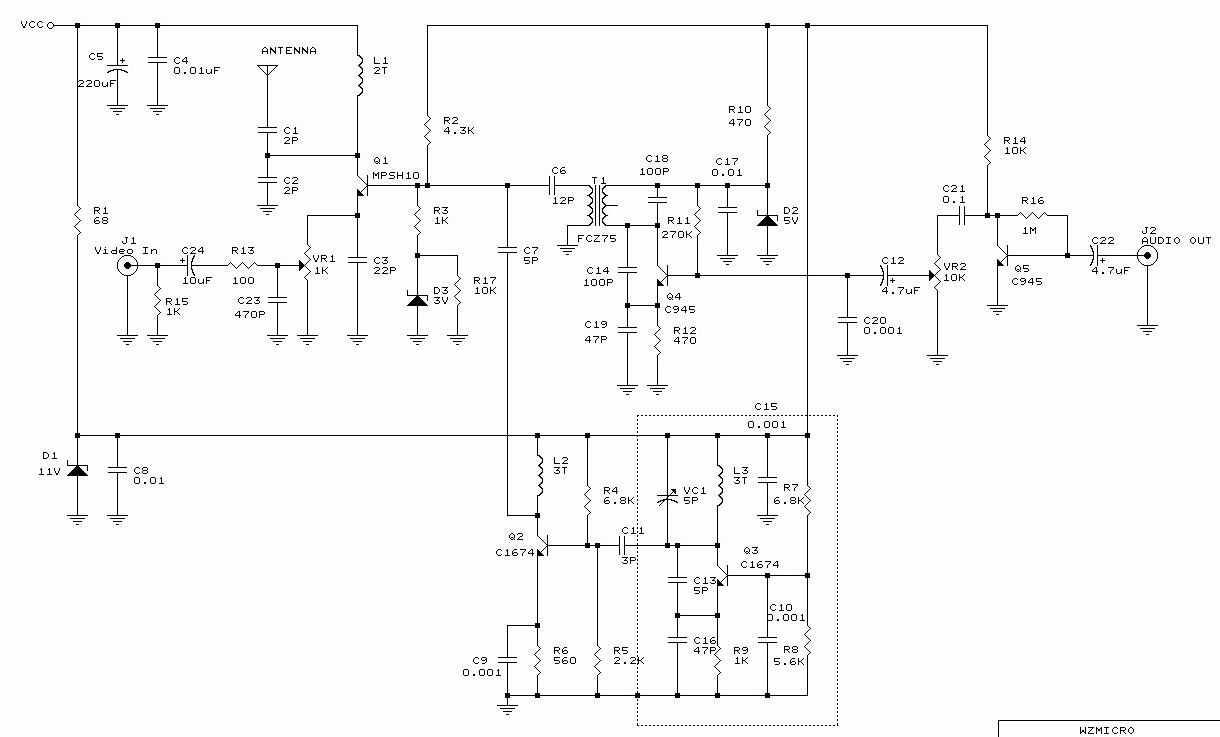
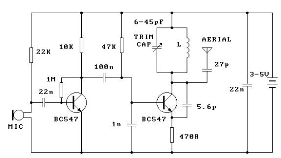
In practical applications, users may find that adjusting the tuning components and the IF transformer can significantly enhance the quality of the received signal. The ability to fine-tune these elements allows for adaptability in various environments and conditions, making the circuit versatile for different use cases. Overall, this wireless transmission circuit is a robust solution for delivering high-quality audio and video signals without the constraints of wired connections.This circuit provides you with wireless audio and visual transmission to a TV. The TV acts as a receiver, eliminating the need to buy a separate monitor. You can also hook it up to a VCR or CCD Camera, and even set up a remote CCTV security system! Q3, VC1, C13, C16 and L3 all make up a colpitts oscillator circuit that fluctuates form 220~250MHz. You can regulate the frequency to any value within this threshold by tuning VC1 or L3. C13 modulates the signal rate. When the capacitance increases, so does the modulation. R9 and C16 bias the local oscillation. If you lower R9`s frequency to 680W the oscillator`s output level will increase. Q2 and L2 act as a frequency doubler. C7, along with FCZ7S3R5 (IF transformer), the Q4 transistor, C14, C19 and R12 all make up the mixer. This mixer takes both audio and visual signals together and "mix" them into one and passes through RF Amplifier Q1 to transmit the signal to the antenna. 1. Turning the blue component`s trimmer on VC1 varies the frequency. When we turn the trimmer, the television`s channel has to be changed accordingly. It is easier to tune the A/V Sender if you have a spectrum analyzer to help you find the correct frequencies.
If the frequency is tuned to 474 MHz then this would be the equivalent of your TV`s channel 14 UHF band. 2. The IF transformer is used to synchronize the audio and video frequency`s level radio. If the TV`s image is too blurry then you can adjust the IFT to fine-tune the image. 🔗 External reference
Related Circuits
Its an adaptation of the 2X 16 LCD project, by adding a ferrite loop antenna, two resistors, and a capacitor. Here the display shows the output of the 10 bit scanning voltmeter with Minimum Mass Wireless Coupler. Both the...
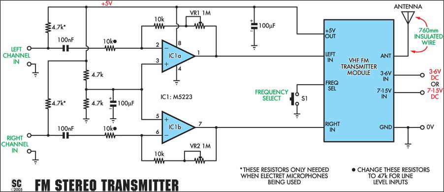
This stereo FM wireless microphone serves as an excellent audio link. Testing revealed a reliable range exceeding 50 meters. It is distinct from previous wireless microphones due to its stereo capability, which delivers unexpectedly high-quality sound. The range was...
Long-range FM transmitter. The power output of most of these circuits is very low because no power amplifier stages were incorporated. The transmitter circuit described here has an. The long-range FM transmitter operates by modulating a carrier frequency with an...

Electronic FM Telephone Transmitter Schematic. The following schematic design illustrates a circuit diagram for an FM telephone transmitter built on a compact PC board layout. This small design allows it to be easily integrated within the housing of a...
This FM transmitter circuit is very simple and has an acceptable transmission range. The signal transmitted from this FM transmitter circuit can be received at almost 300 meters in open air. The circuit requires a 3-volt operating voltage and...

The Subcutaneous Transmitter (A3013) is designed to transmit biometric signals from within the body of a live animal. It serves as the implantable component of the Subcutaneous Transmitter System. The A3013 captures biometric signals using flexible 150-mm leads, digitizes...