
Quiz Circuit

The quiz circuit is designed to provide an interactive experience, relying on the rapid response of participants to activate their respective inputs. The circuit's architecture ensures that only one participant can be recognized at a time, preventing confusion and ensuring a clear winner for each round. The use of CMOS technology in this design allows for low power consumption and high noise immunity, which is essential for reliable operation in various environments.
The bistable latch configuration, utilizing the 4013 D-type flip-flop, serves as the critical element for maintaining the state of the circuit once an input has been activated. The flip-flop's ability to retain its state until reset ensures that the circuit operates predictably, with the output LEDs providing immediate visual feedback to participants.
The integration of the 4082 AND gate allows for the combination of the NOT Q outputs, which helps in establishing a control signal that disables all other inputs once one has been activated. This mechanism is crucial for maintaining the integrity of the quiz format, ensuring that only one LED is lit at a time.
Furthermore, the choice of using non-latching push-button switches simplifies the user interface, making the circuit more accessible for participants who may not be familiar with electronic devices. The recommendation for heavy-duty switches emphasizes the importance of durability in the design, considering the potential for repeated use in a quiz or game show setting.
Overall, this circuit design exemplifies a practical application of digital electronics principles, providing a robust and engaging solution for quiz-based interactions. The flexibility in output options, alongside the straightforward reset mechanism, makes it suitable for various applications, from educational tools to entertainment systems.I`ve had a few requests for a quiz circuit, so here is a 4 input design which can easily be modified. Maybe, I should write the application notes in the style of a game show host. This design uses four IC`s and has four input circuits and four independent outputs and a single master reset switch.
The outputs here are LED`s but may be modified to d rive lamps or buzzers. Only one output LED can be lit at any time. The first person to press their input switch, A, B, C, D will light the corresponding output LED, disabling the other inputs. The circuit uses all CMOS IC`s part numbers shown on the diagram. The supply voltage may be anything between 3 and 15 volts. Alternatively, it may be built using equivalent TTL IC`s and powered on 5 volts. The main component in this circuit is a bistable latch, here it is based on the dual 4013 D-type flip flop.
Pressing the reset switch will clear all flip flops and extinguish any lit LED`s. Under this condition the Q outputs will all be low (logic 0) and NOT Q outputs will be high (logic 1). All four NOT Q outputs are fed to a 4 input AND gate, the 4082 whose output will also be high. The output of the 4082 is wired to one input of each 2 input AND gate (4081). Switch inputs A, B, C, D are all non latching push button switches, the first person to press their switch will cause the corresponding AND gate (4081) to go high and trigger the preset input of the 4013 D-type flip flop.
This will latch and light the appropriate LED. Also the triggered flip flop will have its NOT Q output, set at low, this changes the 4082 output to low and prevents any further triggering of the other flip flops. Switch contact de-bouncing is not required as the first press will latch one of the bistables. Pressing the reset switch, restores the circuit to its former state. I would recommend using heavy duty push button switches, as in use they are likely to be under some stress.
We aim to transmit more information by carrying articles. Please send us an E-mail to wanghuali@hqew. net within 15 days if we are involved in the problems of article content, copyright or other problems. We will delete it soon. 🔗 External reference
Related Circuits
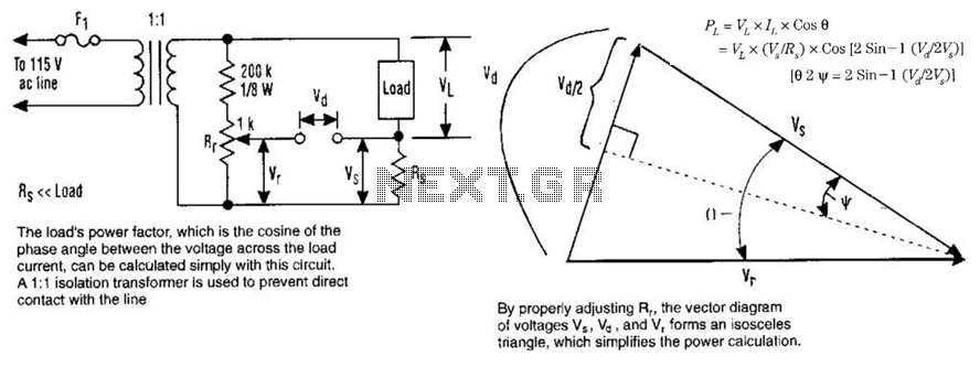
The load's power factor, defined as the cosine of the phase angle between the voltage across the load and the load current, can be calculated using this circuit. An isolation transformer with a 1:1 ratio is employed to prevent...
This compact single-chip circuit is designed for measuring the level of electrically conductive fluids or liquids. It functions as a voltage level sensor and employs an AC bias supply to prevent electrolysis of the probes, thereby enhancing their lifespan....

The TDA4866 is a 90-color power amplifier designed for vertical deflection systems, operating at a frequency range of 50 to 160 Hz. The CRMM circuit is implemented to ensure a high current drive input. The amplifier features a dual...
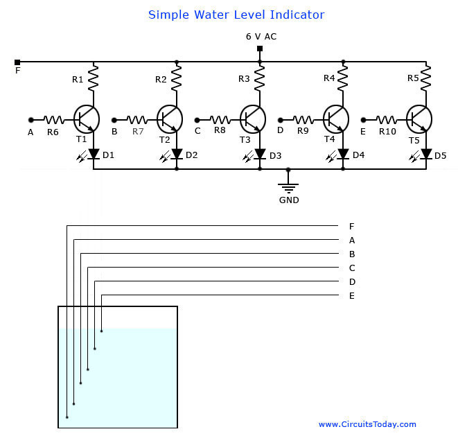
A simple water level indicator project with a circuit diagram for home and industry. This water tank level sensor can be utilized for any liquid level indicator projects. The water level indicator circuit is designed to monitor and display the...
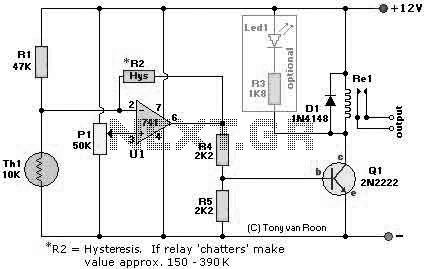
The following page outlines detail information on how to step by step design a Simple Heat Sensor Circuit. This circuit design utilized LM741 as the operational amplifier. More: Circuit Parts/Components List: Re1 = 12V relay R1 = 47K R2...
Servo motors are utilized in various applications, including robotics, puppetry, photography, and more. These compact motors can adjust their output shaft to a specified position on command and maintain that position. Most servos offer a range of motion of...