
servo circuit
This circuit utilizes a 555 timer in astable mode to generate a pulse-width modulation (PWM) signal that controls the servo motor's position. The 555 timer is configured to produce a square wave output, which can be adjusted by varying the resistance of the potentiometer. The duty cycle of the PWM signal determines the angle of the servo motor's shaft, allowing for precise control over its position.
The circuit typically consists of the following components: a 555 timer IC, resistors, a potentiometer, a capacitor, and the servo motor itself. The potentiometer serves as an adjustable input, allowing the user to set the desired position of the servo. The output from the 555 timer is fed into the control wire of the servo, which interprets the PWM signal to position its shaft accordingly.
In practice, when the potentiometer is turned, it alters the resistance in the circuit, which in turn changes the timing of the 555 timer's output. This results in a variation of the pulse width, thus controlling the angle of the servo motor. The capacitor in the circuit helps to stabilize the signal and filter out any noise, ensuring smooth operation.
This type of circuit is advantageous due to its simplicity and low component count, making it accessible for hobbyists and educators. It serves as an excellent introduction to the principles of PWM control and the operation of servo motors, showcasing their versatility in various applications. The original publication in Popular Electronics highlights its relevance and utility in electronics education and practical applications.Servo motors have many uses in everything from robotics to puppetry to photography and beyond. These little motors can position their output shaft to any position on command and hold that position. Most servos have a range of motion to about 210 degrees and thankfully are very easy to control with a simple circuit such as the one presented here.
U sing just a 555 timer and a few support components this circuit can control a servo through it`s full rotation based on the position of a pot. This circuit was originally published in the Think Tank column of the October 1995 issue of Popular Electronics.
🔗 External reference
Related Circuits
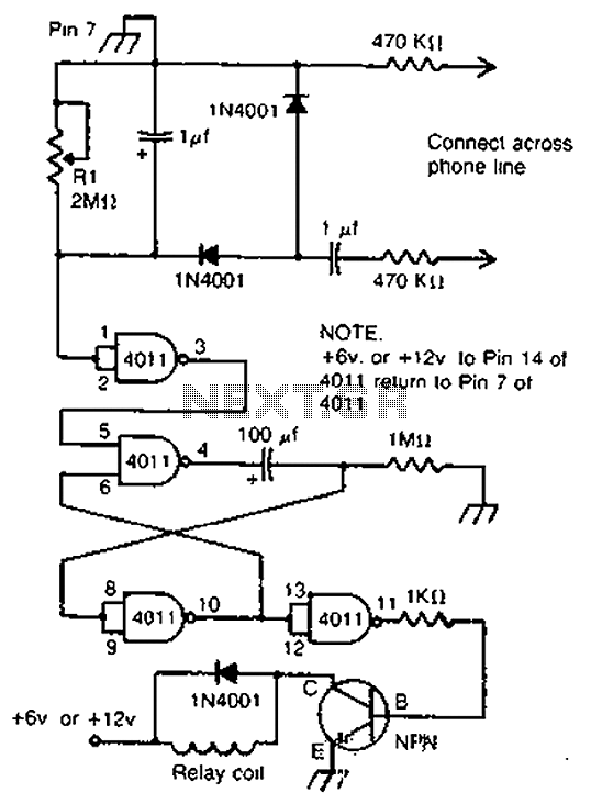
By cross-connecting the telephone ringing circuit, when the phone rings, the circuit activates the relay. It utilizes a delay in contact to drive various devices such as bells, sirens, buzzers, or lights. The telephone ringing circuit is designed to detect...
This integrated circuit (IC) requires fewer external components, making it simpler for beginners to assemble it on a veroboard. The original circuit was sourced from its datasheet. A slightly modified version of the circuit is presented below. This circuit...
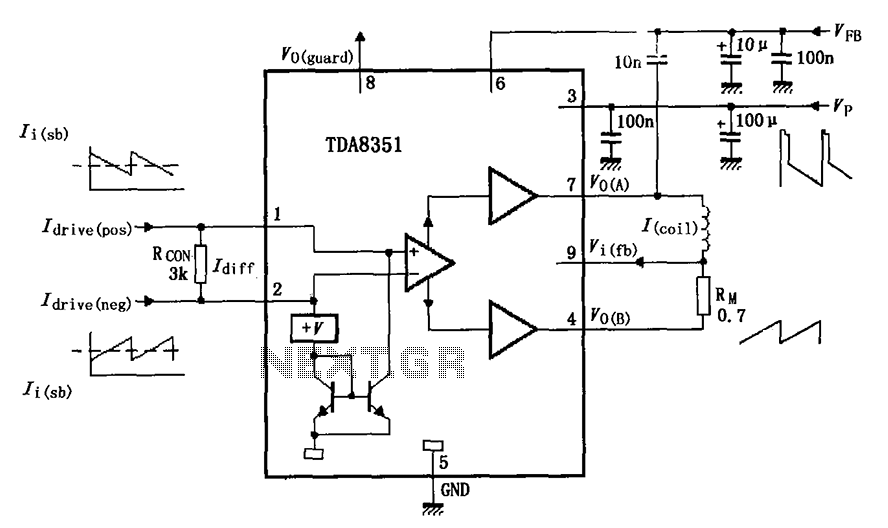
The figure illustrates the actual application circuit for the TDA8351/8356. In this circuit, a 50V voltage feedback (VFB) is connected in series with a 33-ohm resistor. Signals are input at pins 1 and 2, where pin 1 receives a...
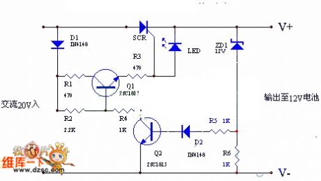
The circuit utilizes the positive half-cycle of an alternating current (AC) to charge a battery. It offers a rapid charging speed and has the potential to extend battery life. This charger is commonly used with standard motorcycles, demonstrating excellent...
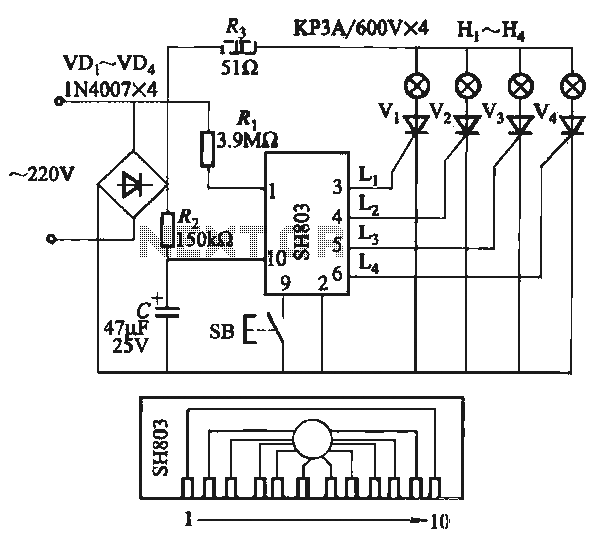
The circuit utilizes the SH803 flash IC, which can store eight different programs and offers various dimming options and light speed adjustments. A button is provided to trigger the control terminal SB on the 9-pin connector for program selection,...
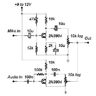
This two-channel audio mixer utilizes 2N3904 transistors to create two preamplifiers. The first preamplifier is designed for high gain, suitable for microphone input, while the second preamplifier allows for control over the audio level input. The audio mixer requires...