
Heat Sensor Circuit using LM741
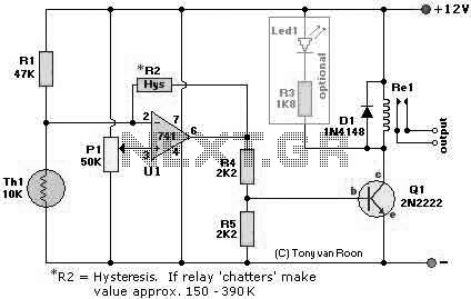
The Simple Heat Sensor Circuit is designed to detect temperature changes and can activate a relay when a specific temperature threshold is exceeded. The circuit primarily employs the LM741 operational amplifier, which serves as a comparator to process the input signals from the temperature sensor.
The components used in the circuit include:
- **Re1 (Relay 12V)**: This relay acts as a switch that is controlled by the output of the LM741. When the temperature exceeds the set point, the relay will close, allowing current to flow through connected devices, such as a fan or alarm system.
- **R1 (47K ohm resistor)**: This resistor is part of the input stage of the circuit and helps set the gain of the operational amplifier.
- **R2 (150K and 390K ohm resistors)**: These resistors are used to form a voltage divider or to set reference voltages for the operational amplifier, ensuring that it operates within the desired voltage range.
- **R3 (1.8K ohm resistor)**: This resistor may be used in conjunction with the other resistors to stabilize the circuit and control the feedback loop of the operational amplifier.
- **R4 and R5 (2.2K ohm resistors)**: These resistors are likely used for biasing purposes or as part of the feedback network for the operational amplifier.
- **P1 (50K Trimmer Potentiometer)**: This adjustable resistor allows for fine-tuning of the circuit's sensitivity, enabling the user to set the temperature threshold at which the relay will activate.
- **IC1 (LM741)**: The LM741 operational amplifier is the core of the circuit, functioning as a comparator. It compares the voltage from the temperature sensor (Th1) with a reference voltage set by the resistors. When the input voltage exceeds the reference voltage, the output of the LM741 changes state, triggering the relay.
- **Q1 (2N2222 or 2N3904 Transistor)**: This transistor acts as a switch that can amplify the current driving the relay, ensuring that it operates effectively without being overloaded.
- **D1 (1N4148 Diode)**: This diode is used for flyback protection across the relay coil, preventing voltage spikes that could damage other components when the relay is de-energized.
- **Th1 (10K Thermistor)**: This temperature sensor changes its resistance with temperature variations. It is the primary component that detects changes in heat, providing the input signal to the operational amplifier.
The design of the circuit allows for a straightforward assembly and tuning process, making it suitable for various applications such as temperature monitoring systems, HVAC controls, or safety alarms. Proper attention should be given to the power supply requirements and the layout of the components to ensure optimal performance and reliability of the heat sensor circuit.The following page outlines detail information on how to step by step design a Simple Heat Sensor Circuit. This circuit design utilized LM741 as the operational amplifier. Circuit Parts/Components List: Re1 = 12V relay R1 = 47K R2 = 150 390K R3 = 1K8, R4, R5 = 2K2 P1 = 50K Trimmer Pot IC1 = LM741, LM741CN-ND, LM741CN, NE741, μA741, etc. Q1 = 2N2222 2N2222 2N3904-ND D1 = 1N4148 Th1 = 10K 🔗 External reference
Related Circuits

These circuits are commonly utilized in robotics to enable DC motors to operate in both forward and reverse directions, as well as to provide an electric brake (short circuit condition). H-bridges can be found as integrated circuits or can...
This innovative buzzer circuit incorporates a relay connected in series with a small audio transformer and a speaker. When the switch is activated, the relay is energized through the primary winding of the transformer and the closed relay contact....
Microdot - wrist watch LED pattern timepiece. This project is a circuit board designed for creating a wristwatch-sized version. The Microdot wristwatch project involves the design and implementation of a compact circuit board that integrates LED technology to display time...
The circuit was designed to create an alarm system that alerts a sleeping person to prevent snoring by utilizing a vibrator instead of an audio alert. The circuit operates on the principle of detecting snoring sounds through a microphone or...
Consider a simplified circuit of a typical relay, which is usually part of a three-phase circuit with a complex contact system. The provided diagram illustrates a single-phase simplified circuit to clarify the basic operation of a relay. Part A...

This is an update to Mr. Hareendran's PIR Sensor Security Light circuit. It has a limitation that restricts the relay voltage to approximately 3.3V. While this may work with some 5V relays, it is not compatible with all. The...