
RMS to DC Converter

The LTC1966 is a highly efficient and precise device ideal for applications requiring accurate measurement of RMS values in various AC signal conditions. Its delta-sigma conversion technology ensures that even complex waveforms can be processed with minimal error, making it suitable for a wide range of electronic measurement applications. The low power consumption of 170 µA makes it particularly advantageous for battery-operated devices, extending battery life while maintaining measurement accuracy.
The device's ability to handle input voltages across the supply rails enhances its versatility, allowing it to be integrated into various circuit designs without the need for additional components to limit input voltage. This feature is particularly beneficial in applications where the input signal may vary significantly, ensuring reliable operation across different conditions.
The high input impedance of the LTC1966 minimizes loading effects on the signal source, preserving the integrity of the measured signal. Coupling capacitors can be employed to isolate the AC signal and prevent DC offset issues, ensuring that the RMS value accurately reflects the true power of the alternating signal.
The adjustable output voltage capability through the OUTRTN pin allows for seamless integration with other measurement systems, such as LCD multimeters. This adaptability is crucial in designing user-friendly measurement devices that require precise output scaling.
In summary, the LTC1966 represents a significant advancement in RMS to DC conversion technology, providing high accuracy, low power consumption, and compact design, making it an excellent choice for engineers and designers in the field of electronic measurement.In order to measure the RMS value of an alternating voltage an accurate converter is required to produce the true RMS value of its alternating input as a DC output. With simple sine-wave inputs the RMS voltage can simply be calculated as 0. 707 times the peak AC voltage, but with complex waveforms the calculation is not nearly as straightforward.
T he RMS value is defined as the DC voltage that would give the same heating effect in a resistor as the alternating voltage. The LTC 1966 from Linear Technology ( uses a new form of delta-sigma conversion and is designed for battery operation, drawing only 170 µA from the supply.
The new technique is accurate to 0. 02 % between 50 mV and 350 mV and is highly linear. It can operate from 50 Hz to 1 kHz (with an error of 0. 25 %) and up to 6 kHz with a 1 % error. The input voltage range on the differential inputs IN1 and IN2 extends to the supply rails, and so in the non-symmetrical circuit shown here the voltage on IN1 can swing between 0 V and the supply voltage. If the signal to be measured is AC only, then another coupling capacitor will be required. The input impedance is many megohms. The output voltage at the OUT pin can be offset by applying a DC voltage to the OUTRTN pin. This is particularly helpful when using the device with LCD multimeter ICs such as the 7106. A further capacitor is connected to the output which is charged up to the required voltage by the switched-capacitor circuit in the converter.
The capacitor required is ten times smaller than that demanded by previous RMS to DC converter designs. The LTC1966 is not temperature sensitive and is available in an 8-pin MSOP package. It allows a tiny RMS to DC converter to be constructed using just four components. 🔗 External reference
Related Circuits
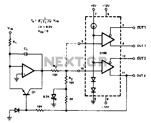
The D169 functions as a level detector, offering complementary outputs. An operational amplifier (op amp) is employed to integrate the input signal Vin, utilizing a time constant defined by the resistor R1 and capacitor C1. A negative input signal...
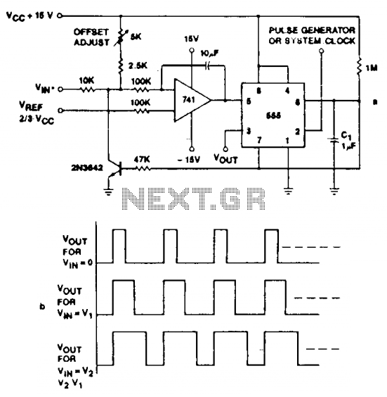
Accuracies better than 1% can be achieved with this circuit (a), and the output signals (b) maintain the original frequency, regardless of the input voltage. Voltage levels can be transformed into pulse durations by integrating an operational amplifier (op...
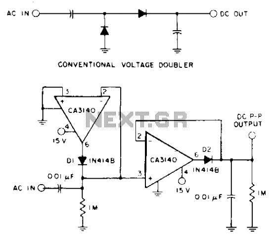
A CA3140 BiMOS operational amplifier, powered by a single positive supply, is employed to convert a traditional voltage doubler utilizing two precision diodes into a precise peak-to-peak AC-to-DC voltage converter. This configuration offers a wide dynamic range and extensive...
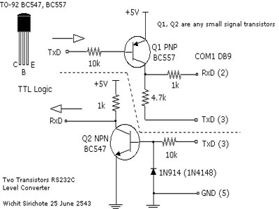
When connecting a microcontroller project to a COM port on a PC, an RS-232 converter is required. Various chips can accomplish this task, such as the MAX232 and DS275. However, for a simple and cost-effective RS-232 converter, the following...
The AD654 is a monolithic voltage-to-frequency (V/F) converter that comprises an input amplifier, a precision oscillator system, and a high-current output stage. A single resistor-capacitor (RC) network is all that is needed to configure any full-scale (FS) frequency up...
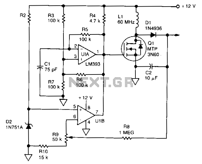
U1 is a dual voltage comparator with open collector outputs. The A side functions as an oscillator operating at 100 kHz, while the B side is part of the regulation circuit that compares a fraction of the output voltage...