
Voltage-to-pulse duration converter
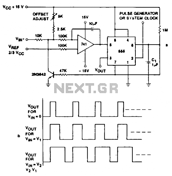
This circuit utilizes an operational amplifier to amplify input voltage levels, which are then processed by a timer IC to generate corresponding pulse durations. The op amp serves as a voltage comparator, where it compares the input voltage against a reference voltage. When the input exceeds the reference level, the op amp output switches states, creating a pulse.
The timer IC, such as the 555 timer, can be configured in monostable mode to produce a single output pulse of a specified duration when triggered by the op amp's output. This duration can be adjusted by varying the resistor and capacitor values connected to the timer, allowing for precise control over the pulse width in relation to the input voltage.
The design ensures that the output frequency remains constant, irrespective of variations in the input voltage, which is crucial for applications requiring stable signal processing. The overall accuracy of the system, exceeding 1%, is achieved through careful selection of components and calibration of the circuit to minimize errors from drift and noise.
This circuit can be employed in various applications, including analog-to-digital conversion, signal conditioning, and timing applications, where accurate pulse generation is essential. The combination of the op amp and timer IC provides a versatile solution for converting voltage levels into precise pulse durations while maintaining signal integrity. Accuracies to better than 1% can be obtained with this circuit (a), and the output signals (b) still retain the original frequency, independent of the input voltage. Voltage levels can be converted to pulse durations by combining an op amp and a timer IC. 🔗 External reference
Related Circuits
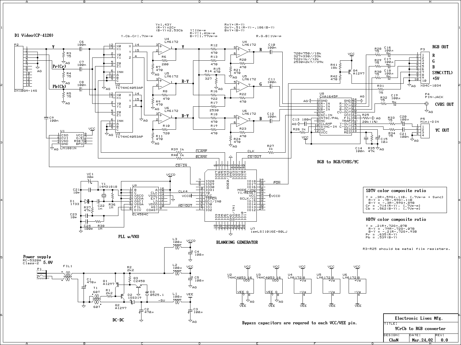
Recently, most digital video equipments, such as video recorder, DVD player and TV game, have component video output. The component video signal is like RGB video signal, but it cannot connect to RGB monitor directly. Thus I designed and...
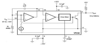
The circuit diagram of a voltage-to-frequency (V/F) converter is presented, designed to handle negative input voltage. It employs the VFC32 voltage-to-frequency converter, which is commonly utilized in various applications. The V/F converter circuit is essential in converting an analog voltage...
The result displayed on the LCD is incorrect; the thermometer shows a reading of 414 degrees instead of the actual room temperature. Assistance is needed to determine whether the issue lies within the hex file or the sensor itself....
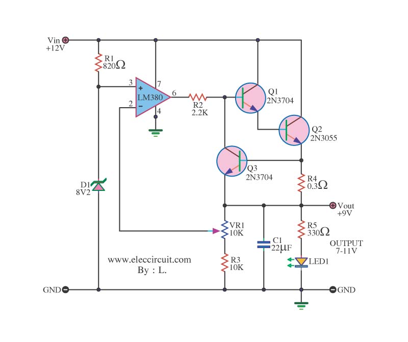
This circuit is designed to modify a power supply input of 12V from a battery or another source. It reduces the voltage level to a stable 9V at a current output of 2 Amps. The circuit utilizes a voltage regulator...
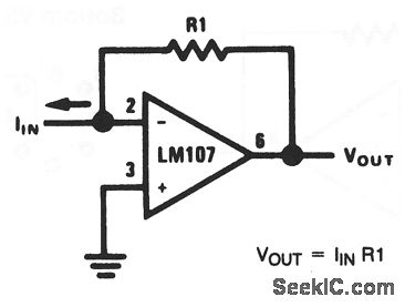
This basic circuit feeds the input current directly into the summing node (pin 2), causing the op-amp output to adjust and extract the same current from the summing node through resistor R1. The scale factor of the circuit is...
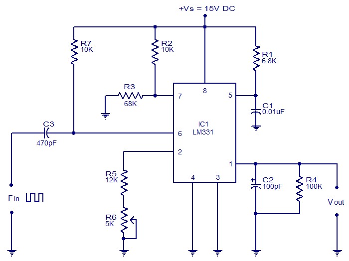
The following circuit illustrates a Frequency Voltage Converter Circuit. This circuit is based on the LM331 IC and operates with a supply voltage of 15V DC. The Frequency Voltage Converter Circuit utilizes the LM331 integrated circuit, which is designed for...