
Remote antenna for 60 kHz (WWVB) reception
 reception")
The described system utilizes an amplifier circuit housed within an outdoor enclosure, which is critical for enhancing the signal received from a designated antenna. The four capacitors on the perfboard play a pivotal role in tuning the receive loop to resonate at the desired frequency, optimizing signal capture. The challenge presented by the physical environment—specifically, the steel and reinforced concrete structure of the office building—complicates the reception of low-frequency signals like the 60 kHz time signal from the NIST station.
To address the inadequate signal reception within the conference room, an external receive antenna is strategically positioned on the building's roof, where the signal strength is significantly better. This antenna is connected to the amplifier circuitry, which boosts the signal before it is transmitted to the conference room. The design must ensure minimal signal loss during transmission, which could be achieved through the use of low-loss coaxial cables and appropriate impedance matching techniques.
Once the amplified signal reaches the conference room, it is coupled to the atomic clocks. This coupling may involve additional circuitry to ensure compatibility between the output of the amplifier and the input requirements of the clocks. The entire setup is designed to provide reliable synchronization of the atomic clocks with the WWVB time signal, thereby overcoming the challenges posed by the building's construction and electronic noise interference. Proper grounding and shielding techniques should also be implemented to further enhance signal integrity and reduce susceptibility to electromagnetic interference.Inside the outdoor box to which the loop is mounted showing the amplifier circuitry. The four capacitors visible at the lower-left corner of the perfboard are used to broadly resonate the receive loop. In the office building in which he worked (a city government building near downtown Salt Lake City) there was a conference room with a pair
of "Atomic Clock" receivers on a middle floor. Being that this was a modern building of steel and reinforced concrete construction, and because it was full of electronic devices such as computers, fluorescent lights, etc. neither of these receivers ever managed to get a good enough signal to synchronize themselves to the 60 kHz time signal being transmitted from Fort Collins, Colorado by the NIST station, WWVB even though the signal from that station here in the Salt Lake area is quite strong.
The solution was to bring a signal into the room from outside, a project that would involve a receive antenna placed in a location that did have a good signal - such as the roof of the building - and then convey it to the conference room and somehow couple it to the clocks in question. 🔗 External reference
Related Circuits
A detailed DIY remote-controlled AC fan regulator with 10-stage speed control. It is built using the ATmega8 microcontroller, and includes full source code and PCB layout. This project involves designing a remote-controlled AC fan regulator that allows users to adjust...
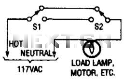
This switching arrangement is utilized in both domestic and industrial environments to enable control of a light or other AC-operated device from multiple locations. This switching arrangement, commonly referred to as a multi-way switching system, is designed to facilitate the...
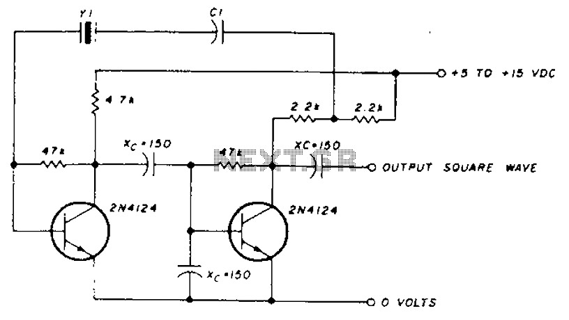
A transistor in series with capacitor C1 can be utilized to adjust the oscillator output frequency. The frequency may vary with changes in capacitance ranging from 20 pF to 0.01 µF, or as determined by the tuning capacitor. The...
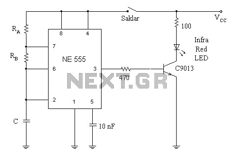
A simple circuit diagram illustrates a schematic for a remote control system, which consists of two components: a transmitter and a receiver. The transmitter circuit is controlled by the NE555 integrated circuit (IC). This system operates by detecting the...
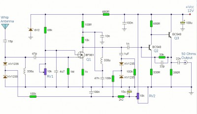
This is a booster antenna circuit designed for frequencies ranging from 550 kHz to 1650 kHz, aimed at amplifying signals received from a telescopic antenna. It covers the medium waveband within this frequency range. To drive low impedance (50...
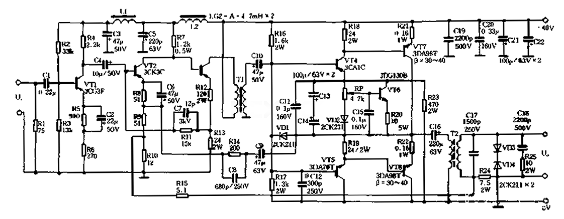
A 20W power amplifier circuit is illustrated in Figure 8-3. It features a pre-release level and enhances the power level through three stages to minimize significant phase shifts in the feedback loop. PNP silicon transistors are selected for both...