
Simple Stepper Motor ControllerCircuit Based On The 7404 IC
The simple stepper motor controller circuit utilizes the 7404 hex inverter IC to control the operation of a stepper motor. The 7404 IC consists of six independent inverters, which can be employed to generate the necessary control signals for the stepper motor. The circuit operates by providing a sequence of pulses to the motor windings, allowing for precise control of the motor's position and speed.
In this configuration, the input signals to the 7404 can be generated by a microcontroller or a simple switch mechanism. The output from the 7404 drives the transistors that act as switches for the motor coils. When a logic high signal is applied to an inverter input, the output goes low, and vice versa, creating a square wave pulse that energizes the motor coils in a specific sequence.
To ensure adequate heat dissipation, it is essential to incorporate heat sinks or other thermal management solutions, especially if the circuit operates at higher currents. The design may also include diodes across the motor coils to protect against back EMF generated when the motor is de-energized, thereby preventing damage to the circuit components.
Overall, this simple stepper motor controller circuit provides an effective method for controlling stepper motors with minimal components, leveraging the capabilities of the 7404 IC for reliable operation.The following circuit shows about Simple Stepper Motor Controller Circuit Diagram. This circuit Based On The 7404 IC. Features: suitable heat .. 🔗 External reference
Related Circuits
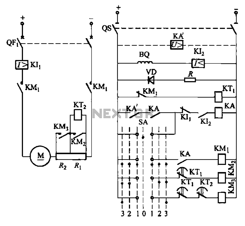
The circuit depicted in Figure 3-190 includes an armature circuit with two startup resistors, Ri and Rz, connected in series through the main switch SA to facilitate starting, stopping, and speed control. During the startup phase, two relays, KTi...
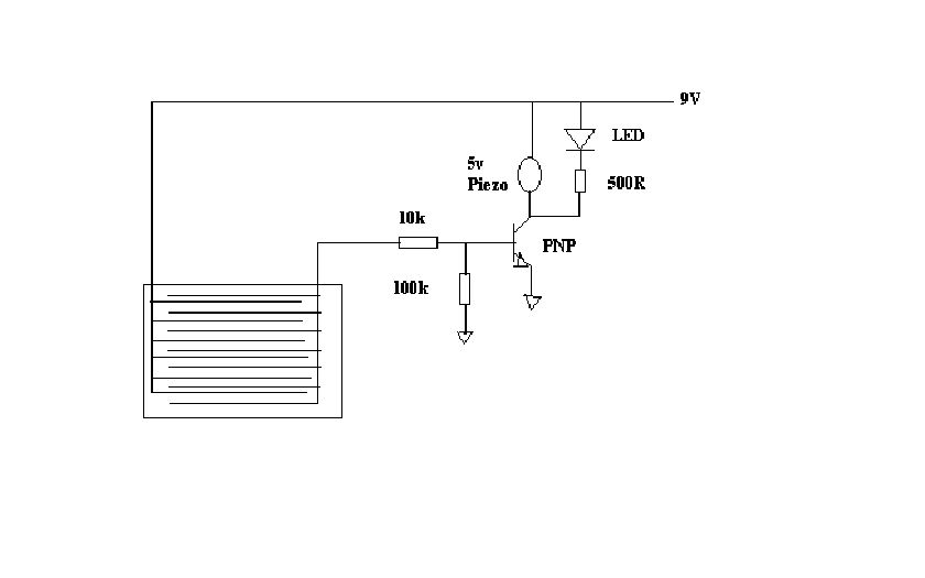
This project outlines a simple water detector circuit. The components required for this project include the following: 1. One IC 555 timer, and 2. A small-sized general-purpose relay. The water detector circuit utilizes the IC 555 timer configured in a...
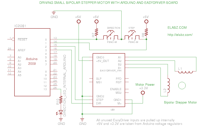
A video and the circuit with schematics for connecting and controlling the world's smallest linear actuator based on a bipolar stepper motor from a Blu-ray drive. The project involves the design and implementation of a circuit to control a linear...
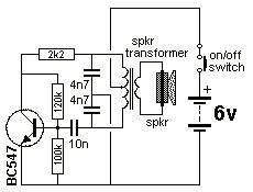
The Colpitts Oscillator is characterized by tapping the mid-point of the capacitive side of the oscillator section. The inductor can be the primary side of a speaker transformer. The feedback comes via the inductor. The Colpitts Oscillator is a type...
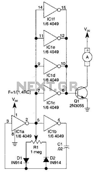
This circuit will drive a small DC motor over a wide range of speeds without stalling by controlling the duty cycle of the motor, rather than the supply voltage. The described circuit utilizes pulse width modulation (PWM) to effectively control...
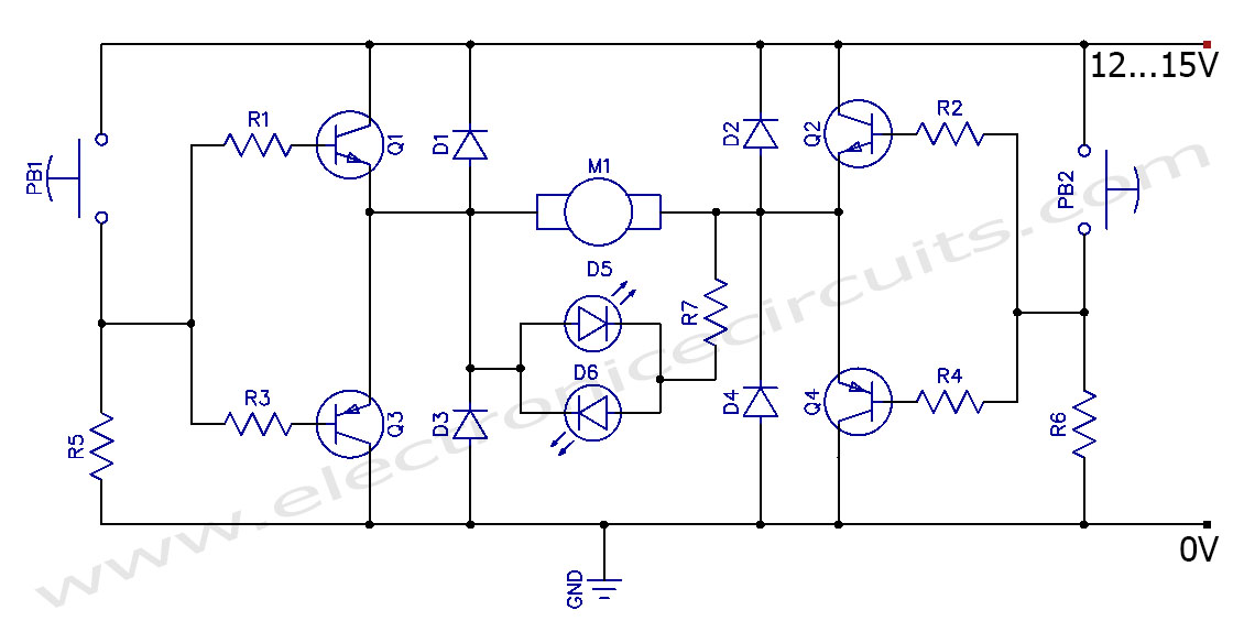
This circuit can control the direction of a DC motor, allowing it to operate in both clockwise and counterclockwise directions (forward and backward). The described circuit employs an H-bridge configuration, which is essential for reversing the polarity of the voltage...