
SIMPLE WATER DETECTOR

The water detector circuit utilizes the IC 555 timer configured in a monostable mode. In this configuration, the timer generates a pulse when water is detected, which activates the relay. The relay can be used to control a larger load, such as an alarm or a pump, depending on the application.
The circuit design begins with the 555 timer, which is powered by a DC voltage source, typically between 5V and 15V. The input to the timer is connected to two probes that serve as the water detection sensors. When water bridges the gap between the probes, it completes the circuit, causing the voltage at the trigger pin of the 555 timer to drop below 1/3 of the supply voltage. This triggers the timer to output a high signal at the output pin.
The output pin is connected to the base of a transistor, which acts as a switch to control the relay. The relay is wired in such a way that it activates when the transistor is turned on, allowing current to flow through the relay coil. This can be used to drive an external device, such as an LED indicator or a water pump.
To ensure the reliability of the circuit, it is important to include a resistor-capacitor (RC) network at the timer's threshold and discharge pins. The values of these components can be adjusted to set the duration of the output pulse, allowing customization of the response time of the water detector.
Overall, this simple water detector circuit is an effective and cost-efficient solution for monitoring water levels or detecting leaks in various applications. Proper assembly and testing of the components will ensure optimal performance and reliability.Hi i am ajinkya this is my first Instructable -SIMPLE WATER DETECTOR For this project u will need the following parts: 1.IC 555 timer-1 2.Small size g.. 🔗 External reference
Related Circuits
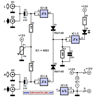
This audio peak detector enables the monitoring of a pair of stereo channels using a single LED. The circuitry employed for both the left and right channels is identical. The audio peak detector circuit is designed to provide a visual...
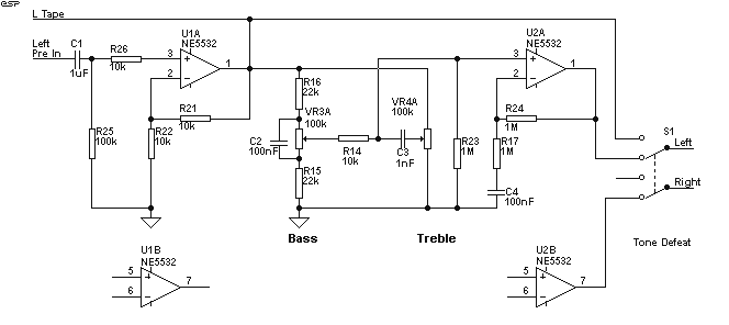
The preamp featured has optional tone and balance controls which may be omitted if desired. The input switching may be extended if needed to accommodate more signal sources. In this version, no RIAA (phono) input is provided. See the...
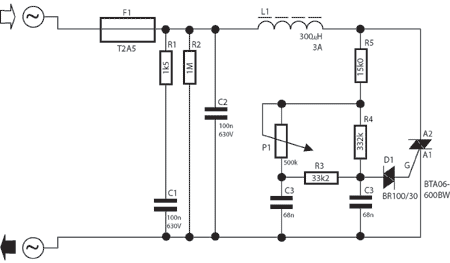
A potentiometer regulates the firing point of the triac. Capacitor C4 is charged through resistors R3, R4, P1, and R5. After a specific duration, determined by the potentiometer setting, the charge in C4 becomes sufficient for the diac D...
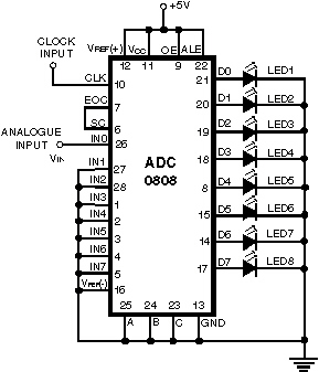
Normally, an analog-to-digital converter (ADC) requires interfacing with a microprocessor to convert analog data into digital format. This involves additional hardware and software, leading to increased complexity and overall cost. The circuit of the A-to-D converter presented here is...
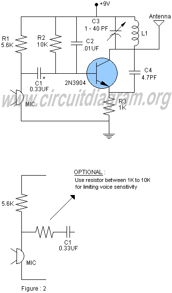
This document provides a schematic and description for constructing an FM transmitter. The circuit is designed to be simple, utilizing minimal components while achieving a long transmission range. The FM transmitter circuit typically consists of a few key components: an...
It's a simple metal detector design that has quite good characteristics. The principle of operation differs from classic schemes (BFO, transmit-receive known as "two-boxes" metal detector, inductive). The dynamic mode is used to find targets in an interference environment....