
Speed Control of DC Motor using Microcontroller 8051 withCircuit

The circuit for this DC motor speed control project consists of several key components: a DC motor, a microcontroller (AT89C51), a power supply, a transistor (typically an NPN type), and a PWM driver circuit. The microcontroller is programmed to output a PWM signal that controls the base of the transistor, which acts as a switch to modulate the power supplied to the motor.
In operation, the microcontroller generates a PWM signal with a specific duty cycle. The duty cycle determines the proportion of time the signal is High versus Low, effectively controlling the average voltage and current supplied to the motor. A higher duty cycle results in increased average voltage, thereby increasing the motor speed, while a lower duty cycle decreases the average voltage and slows the motor down.
The transistor is connected in such a way that it can handle the current required by the motor. When the PWM signal from the microcontroller is High, the transistor turns on, allowing current to flow through the motor. When the PWM signal is Low, the transistor turns off, stopping the current flow. This rapid switching creates the effect of varying the motor speed without the need for complex mechanical systems.
Additional components may include diodes for flyback protection, which prevent back EMF generated by the motor from damaging the transistor and microcontroller. A capacitor may also be included to filter the PWM signal, ensuring smoother operation of the motor.
Overall, this circuit design provides a robust solution for controlling the speed of a DC motor using modern electronic components, allowing for efficient and precise adjustments based on user-defined parameters. The integration of a microcontroller enhances flexibility and programmability, making it suitable for a variety of applications in automation and robotics.The aim of developing this project is to control the speed of DC motor. The main advantage in using a DC motor is that the Speed-Torque relationship can be varied to almost any useful form. To achieve the speed control an electronic technique called Pulse Width Modulation is used which generates High and Low pulses.
These pulses vary the speed in the motor. For the generation of these pulses a microcontroller (AT89c51) is used. As a microcontroller is used setting the speed ranges as per the requirement is easy which is done by changing the duty cycles time period in the program. This project is practical and highly feasible in economic point of view, and has an advantage of running motors of higher ratings.
This project gives a reliable, durable, accurate and efficient way of speed control of a DC motor. 🔗 External reference
Related Circuits
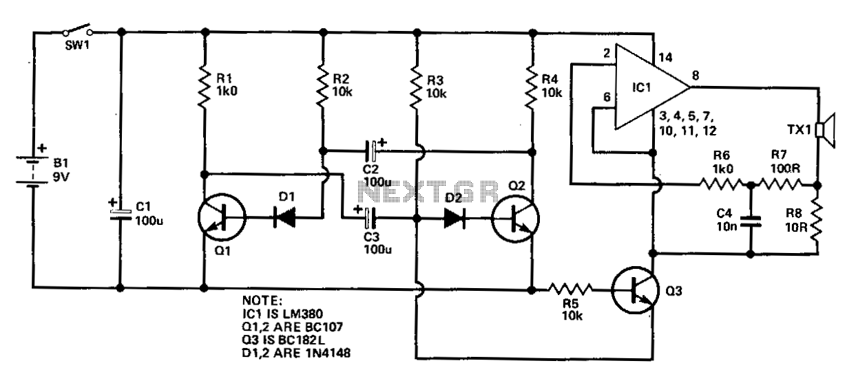
This circuit comprises two fundamental components: an oscillator tuned to 40 kHz and a voltage doubler with a pulse generator. The pulses generated are approximately 10 ms in duration and occur 2-3 times per second to minimize battery consumption...
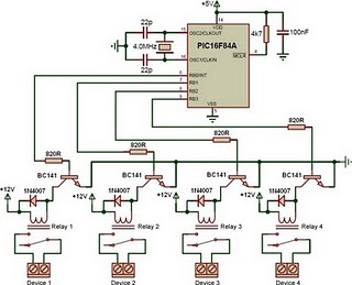
This is a relay driver based on a PIC16F84A microcontroller. The board includes four relays, allowing control of four distinct outputs. The relay driver circuit utilizing the PIC16F84A microcontroller is designed for controlling multiple devices or systems through relay activation....
Automatic fan control circuit. This circuit turns a 12V DC fan or CPU fan on or off based on temperature readings. The temperature can be adjusted using VR1. The automatic fan control circuit operates by monitoring the temperature of...
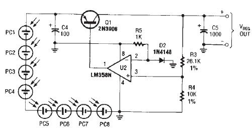
The circuit diagram illustrates a portable solar charger that utilizes an LM358N operational amplifier and a single transistor. This regulator delivers a constant output of 2.4 volts DC, suitable for powering small devices requiring energy from two AA battery...
The circuit diagram presented illustrates an IC-controlled emergency light with a charger, functioning as a 12V to 220V AC inverter circuit. This emergency light circuit is designed to automatically activate in the event of a mains failure, while also...
The control voltage is fed into the first half of a 1458 op-amp, this stage inverts the signal and sets the offset and gain for the right channel gain control circuit. This signal is then fed into the second...