
Portable solar charger designed using LM358N
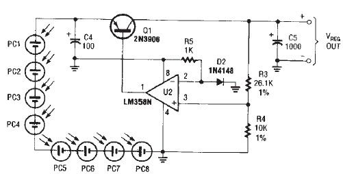
The portable solar charger circuit is designed to efficiently convert solar energy into a usable electrical output for small electronic devices. The core components include the LM358N operational amplifier, which is configured to maintain a stable output voltage of 2.4 volts. This is critical for devices with specific voltage requirements, ensuring reliable operation without damage due to overvoltage.
The inclusion of a transistor serves as a switching element, allowing for control of the current flow from the solar cells to the load. The transistor must be selected based on the expected load current, which, in this case, is capped at 125mA. This current rating is sufficient for devices like portable radios or small LED lights, making the circuit versatile for various applications.
The low dropout voltage of 0.3 volts is particularly advantageous, as it allows the circuit to operate effectively even when the solar cell output is slightly below the required voltage. This characteristic is crucial for maintaining performance during varying sunlight conditions, ensuring that the charger can still function effectively when solar intensity fluctuates.
When selecting solar cells for this application, it is important to consider their voltage and current output characteristics. The solar cells should be capable of providing sufficient voltage to overcome the regulator's dropout voltage while also delivering enough current to meet the load requirements. Typically, a solar panel rated around 5V with sufficient current capacity would be appropriate for this circuit.
Overall, this portable solar charger circuit presents a practical solution for harnessing solar energy for small electronic devices, combining efficiency with simplicity. Proper component selection and circuit design ensure that it operates effectively in real-world conditions, making it a valuable addition to portable power solutions.As you can see in circuit diagram, this portable solar charger circuit, is based on a LM358N operational amplifier and one transistor. This regulator provide a constant 2. 4 volts DC and can be used for powering small devices that needs to be powered from two AA battery cells.
Because the regulator has a low drop down voltage of 0. 3 volt you sho uld take care about this when you choose solar cells. Maximum load current for this solar charger electronic circuit project is around 125mA typically, enough for small portable devices like radios. 🔗 External reference
Related Circuits
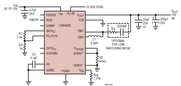
A very simple, high-efficiency switching mode buck-boost power supply circuit can be designed using the LTM4609 switching regulator IC. This circuit will provide a fixed output voltage of 12 volts. As illustrated in the schematic, the switching power supply...
Using a wire connection, utilize the NFA.55 timebase circuit delay type light touch switch, which can directly replace an ordinary mechanical switch without needing to modify the original internal wiring. The circuit is powered back with good hoof Chapter...
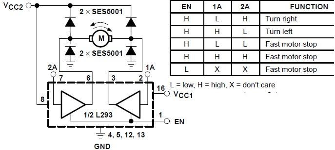
The L293 is designed to provide bidirectional drive currents of up to 1 A at voltages ranging from 4.5 V to 36 V. The L293D variant is capable of delivering bidirectional drive currents of up to 600 mA at...
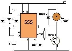
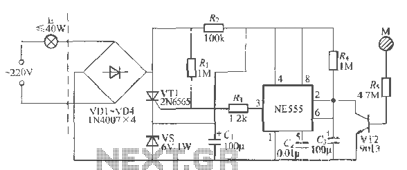
This project utilizes a 555 timer to control the speed of a 6-volt DC motor. Speed adjustment is achieved by rotating a 50 kΩ potentiometer either to the left or right. The circuit employs a 555 timer configured in astable...
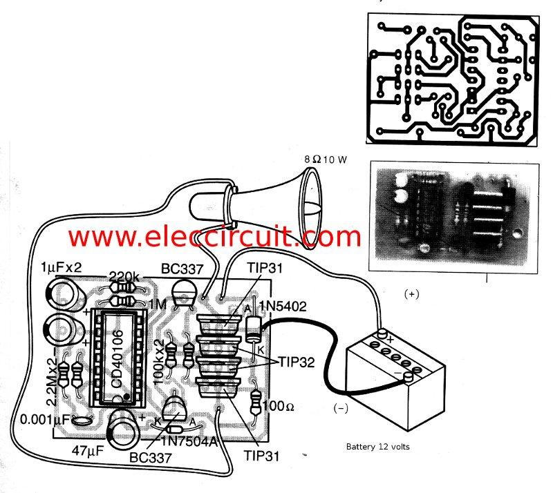
This is a simple siren sound generator with high power output and significant noise. The circuit utilizes digital ICs, specifically the CD4046, in an inverter configuration, along with four transistors to amplify the current output to a horn speaker...
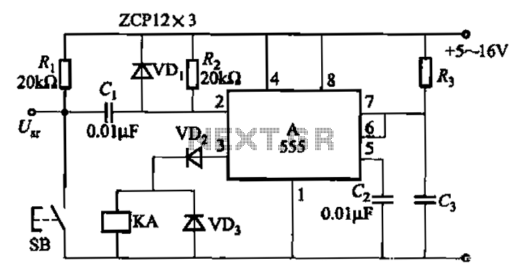
The 555 integrated circuit is utilized in a delay circuit configuration, functioning as a one-shot timer. The delay time can be adjusted using resistor R3 and capacitor C3. Typical values for R3 range from 1 kΩ to 10 MΩ,...
Warning: include(partials/cookie-banner.php): Failed to open stream: Permission denied in /var/www/html/nextgr/view-circuit.php on line 713
Warning: include(): Failed opening 'partials/cookie-banner.php' for inclusion (include_path='.:/usr/share/php') in /var/www/html/nextgr/view-circuit.php on line 713