
Ultra wideband RF detector design challenge

The design of a wideband RF detector incorporating multiple resonant LC tanks offers the capability to capture a broad spectrum of radio frequencies. The LC tank circuits serve as selective filters that resonate at specific frequencies, allowing the detector to identify and process signals within the designated frequency ranges.
The proposed configuration suggests employing a series of LC tank circuits, each tuned to different frequencies spaced 5 to 10 MHz apart. This spacing is crucial for ensuring that the detector can effectively cover a wide frequency range while maintaining sensitivity to the desired signals. The exception of 1 MHz spacing from 9 MHz indicates a focus on finer resolution in that specific frequency band, which may be relevant for applications requiring precise detection in that range.
Each LC tank circuit consists of an inductor (L) and a capacitor (C) arranged to form a resonant circuit. The resonant frequency (f) of each tank is determined by the formula:
f = 1 / (2π√(LC))
Where L is the inductance in henries and C is the capacitance in farads. By selecting appropriate values for L and C, the desired resonant frequencies can be achieved.
The output from each LC tank can be fed into a common detection stage, which may include a diode for envelope detection or a more complex demodulation circuit, depending on the intended application. The output signals can then be processed further for amplitude measurement or converted to a digital format for display or analysis.
In summary, the design of a wideband RF detector using resonant LC tanks provides a versatile solution for RF signal detection across a broad frequency range, with specific tuning to enhance performance in critical areas of interest. Proper component selection and circuit design will ensure optimal functionality and sensitivity of the detector.I`d like to make a wideband RF detector. I`m thinking of using a range of resonant LC tanks, 5 to 10 mhz apart, (except / or 1 mhz apart from 9 to.. 🔗 External reference
Related Circuits
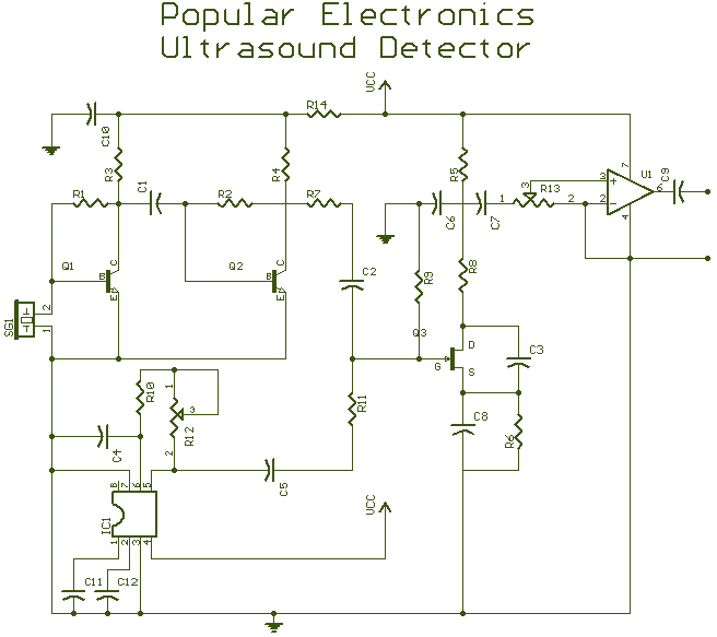
The bat ultrasounds are picked up by the microphone SPKR1 and go through two stages of amplification at Q1 and Q2. Separately, a tunable (R12) single frequency is produced by the LM567 oscillator U1. The LM567 is a tone...
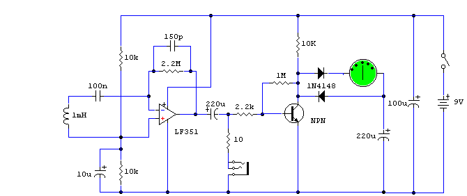
This circuit is easy to assemble and exhibits higher sensitivity than many commercially available devices. This circuit design features a simple yet effective configuration that enhances its sensitivity, making it suitable for various applications. The circuit typically includes key components...
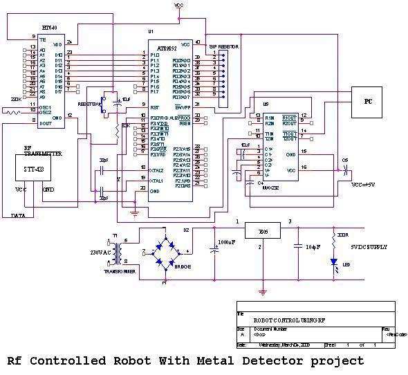
An embedded C-based RF-controlled robot equipped with a metal detector, along with wireless image and voice transmission capabilities. This project report is intended for electronics and communication engineering students. The project involves the design and implementation of an RF-controlled robot...
Dynamic flip-flops disregard input pulses that are shorter than 40 ns or do not conform to TTL voltage levels. Consequently, TTL flip-flops are not well-suited for certain applications. Dynamic flip-flops are a specific type of sequential logic circuit that utilize dynamic...
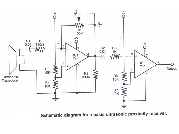
This section provides step-by-step instructions, accompanied by photos, for constructing an Ultrasonic Proximity Receiver. As this circuit is quite simple, only a schematic for the sensor is presented here. The objective of this tutorial is to assist others in...
The metal detector described in the example can detect metal objects made of highly permeable magnetic substances. The circuit operates based on several components: a power circuit, a sine wave oscillator, a PLL (phase-locked loop) circuit, and a hybrid...