
Metal detector 2

The metal detector circuit is designed to efficiently identify metal objects by utilizing a combination of electronic components that work in unison. The power circuit is crucial for supplying the necessary voltage and current to the entire system, ensuring that all components operate effectively. The inclusion of filter capacitors (Cl and C2) helps to stabilize the power supply by reducing voltage fluctuations, which is essential for maintaining the performance of sensitive electronic circuits.
The sine wave oscillator circuit plays a pivotal role in generating the alternating current (AC) signal that is necessary for the operation of the detecting coil (L). This coil is responsible for creating a magnetic field that interacts with nearby metal objects. The oscillation frequency can be adjusted by changing the values of capacitors (C3-C5) and resistors (Rl and R2), allowing for fine-tuning of the detector's sensitivity and range.
The PLL circuit is essential for maintaining a consistent frequency and phase relationship between the transmitted and received signals. It utilizes a dual time-base integrated circuit, which helps in demodulating the signal received from the detecting coil. The resistors (R3) and potentiometers (RPl) in this circuit allow for precise adjustments to the loop characteristics, enhancing the detector's ability to differentiate between various types of metal.
The hybrid amplification circuit is designed to amplify the weak signals received from the detecting coil. This is achieved through the use of transistors (V2 and V3) and resistors (R4-R6), which boost the signal strength to a level that can be accurately measured by the ammeter (PA). The potentiometer (RP2) allows for further adjustment of the amplification level, providing the user with control over the sensitivity of the detector.
Overall, this metal detector circuit exemplifies a well-structured approach to metal detection, employing a range of electronic components that work together to achieve effective and reliable performance. The careful selection of resistors, capacitors, and other components ensures that the circuit operates within its intended parameters, making it suitable for various applications in metal detection.This metal detectors described in the example can be used to detect metal objects with high permeable magnetic substances. The working principle. The metal detector circuit is composed of the power circuit, sine wave oscillator, PLL phase-locked loop circuit and hybrid amplification circuit, it is shown in Figure 8-68.
Power circuit is composed of the battery GBl, GB2, filter capacitor Cl, C2, and the power switch S (Sa, Sb). Sinusoidal oscillator circuit consists of transistors Vl, detecting coil L, capacitor C3-C5 and resistors Rl, R2. PLL circuit is composed of dual time-base integrated circuit and resistors R3, potentiometers RPI, capacitors C6-C8.
The hybrid amplification circuit is composed of the transistors V2, V3, resistors R4-R6, potentiometer RP2 and ammeter PA. Rl-R6 use l/8W or 1/4W carbon film resistors. RPl uses multi-turn precision potentiometer; RP2 uses general lap synthetic membranes potentiometer. Cl and C2 select electrolytic capacitors with voltage in 16V; C3-C5 and C8 select monolithic capacitors; C6 and C7 select high-frequency ceramic capacitors.
🔗 External reference
Related Circuits
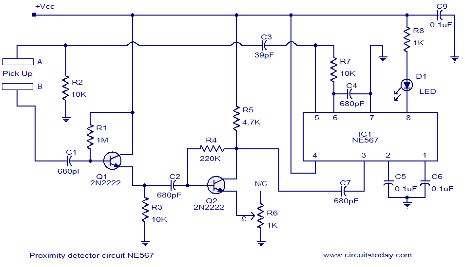
A simple proximity detector circuit utilizing the NE567 integrated circuit (IC). The circuit activates an LED when an object approaches the sensor. The NE567 is a versatile phase-locked loop (PLL) device commonly used for applications such as proximity detection due...
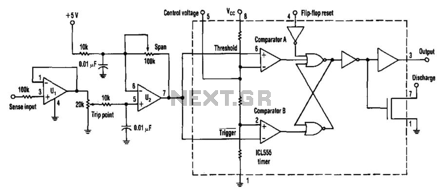
Many applications require analog signals to be sensed and digital signals to be controlled. A way to detect these points is by using a 555 timer in an unconventional configuration. This method will also add hysteresis to the circuit...

The 555 timer is configured as a monostable multivibrator that requires a negative-going trigger. If the input pulse is positive-going, it can be inverted using an inverter circuit, which can be constructed with either an inverting gate or a...
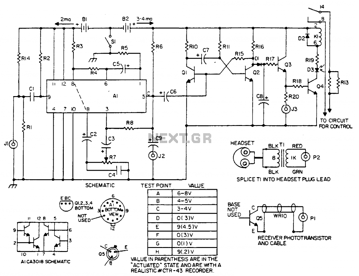
The laser light detector employs a sensitive phototransistor (Q5) positioned at the focal point of a lens (LE2). The output from Q5 is directed to a sensitive amplifier composed of an array (A1), which is biased through a voltage...
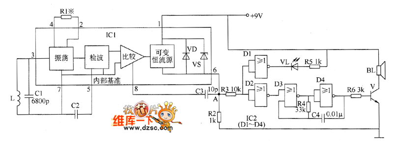
The metal detector circuit comprises an oscillator and a sound-light alarm circuit. The oscillator circuit includes an inductor (L), a capacitor (C1), a sensor switch integrated circuit (IC1) that integrates the oscillator, detector, comparator circuit, and peripheral components. The...
This post discusses a proximity detector circuit primarily utilizing the NE555 integrated circuit (IC). The circuit is designed for burglar alarms based on beam interruption, with the advantage that the transmitter and receiver are contained within the same enclosure,...