
Using FET 2n3819 simple audio mixer circuit
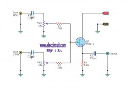
This mixer circuit is designed to combine two audio signal channels into a single mono output, making it suitable for various audio applications where space and power consumption are critical. The codec circuit serves as the primary component for converting stereo signals into a mono format, ensuring that the output is compatible with mono audio systems.
The addition of variable resistors VR1 and VR2 allows for fine-tuning of the audio levels from each input channel, providing flexibility in balancing the audio mix. Resistor R1 and capacitor C1 can be used to adjust the frequency response or gain of the circuit, depending on the specific requirements of the application. The circuit's low power consumption is advantageous for portable devices powered by 9-volt batteries, ensuring extended operation without frequent battery replacements.
When the audio signal enters the circuit, it is first coupled through capacitors C1 and C2, which serve to block any DC offset and allow only the AC audio signal to pass through. This coupling is critical in preventing distortion and ensuring that only the desired audio frequencies are processed. The signals are then directed to the variable resistors, where the user can adjust the volume levels before they reach the FET Q1.
The FET (Field Effect Transistor) Q1 acts as an amplifier, boosting the audio signal to a usable level for output. After amplification, the signal is sent through capacitor C3, which again serves as a coupling capacitor to ensure that any DC component is blocked from reaching the output stage. This final coupling stage is essential for maintaining signal integrity and ensuring that the output is clean and free from unwanted noise.
Overall, this simple mixer circuit is an effective solution for combining audio signals while maintaining low power consumption and allowing for user-adjustable audio levels. Its design is suitable for various applications, including portable audio devices, DIY audio projects, and other scenarios where space and power efficiency are paramount.This circuit, a simple mixer circuit. It can mix two signal channels and one channel is output. Using a codec circuit, Convert stereo audio to mono audio time. It can increase the number of channels too. By adding a VR1, R1 and C1 to the amount needed. Then connected to Buffett a new one. Most importantly is eating circuit current is very low. Can use with 9-volt batteries immediately. When entering voice signal, one of input 1 and input 2. Audio is via C1 and C2 of each channel, served coupling signals to VR1 and VR2. To adjust the audio to the Fet Q1. Which it serves, including audio. Then expand signal the output pin S through C3 For coupling signal again, before leaving to the output. 🔗 External reference
Related Circuits
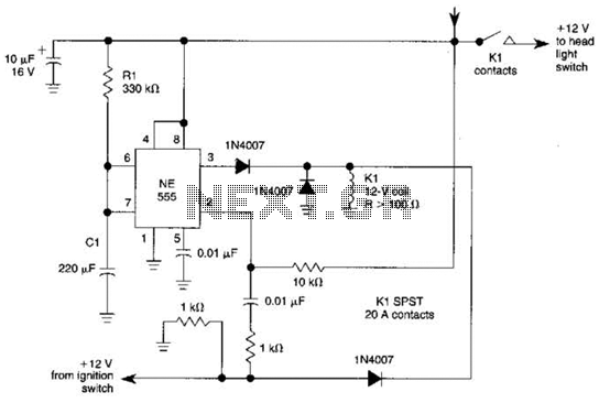
When the ignition switch is activated, relay K1 receives continuous power, allowing the headlights to be turned on. When the ignition is turned off, timer IC1 is activated, maintaining its power for a duration determined by resistor R1 and...
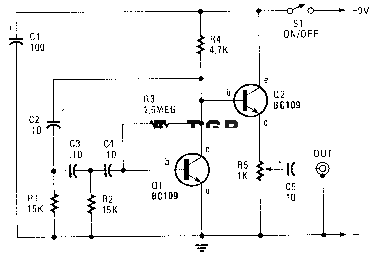
This circuit generates a sinusoidal output of approximately 8 V peak-to-peak, which can be adjusted down to zero, operating at a frequency of about 500 Hz. The signal is produced by a phase-shift oscillator. The described circuit utilizes a phase-shift...
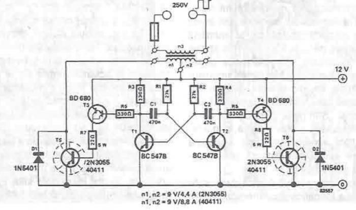
A simple portable converter that transforms 12V to 250V can be constructed using this circuit diagram. This converter is intended for portable use with a 12V car battery. A built astable multivibrator, consisting of transistors T1 and T2, generates...
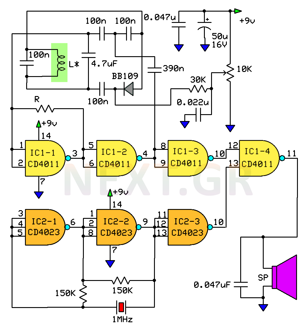
This circuit is a metal detector designed to detect large metallic objects at depths ranging from 2 to 3 meters, depending on the size of the object and the type of soil. The construction is straightforward, making it accessible...
White noise (the sound you hear when a TV is tuned to a non-existent station) has a frequency characteristic which raises the power level by 3dB with each increasing octave, and is not suitable for response testing (and will...
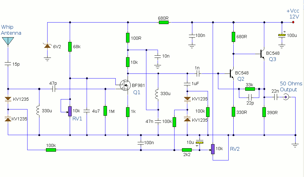
The antenna amplifier circuit comprises approximately 40 components, featuring two NPN transistors (BC548), one MOSFET (BF981), two varicap diodes (KV1235), and a 6.2V zener diode. It includes a 330µH inductor/coil, which can be modified for operation on different frequency...