
Active AM Radio Antenna Amplifier / Preamplifier Circuit
The antenna amplifier circuit is designed to enhance the reception capabilities of AM radio receivers by amplifying weak signals from a telescopic whip antenna. The use of two NPN transistors and a MOSFET allows for efficient signal processing, while the varicap diodes enable fine-tuning of the frequency response. The 330µH inductor/coil serves as a critical component for tuning across the medium waveband, providing flexibility for different frequency ranges.
The gain control feature, facilitated by RV1, allows users to adjust the amplification level based on signal strength. This is particularly useful in environments with varying signal conditions, enabling optimal reception without distortion from strong signals. The output impedance of 50 ohms ensures compatibility with standard radio receivers, facilitating straightforward integration into existing systems.
The dual-gate MOSFET configuration not only enhances selectivity but also improves overall performance through its ability to handle varying input signals effectively. The zener diode provides stability to the power supply, ensuring consistent performance of the amplifier circuit. The composite amplifier configuration, utilizing Q2 and Q3, further enhances the circuit's ability to drive low impedance loads, making it suitable for a wide range of applications.
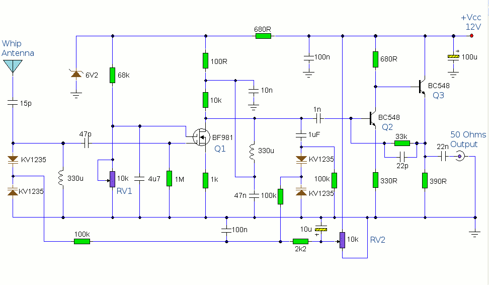
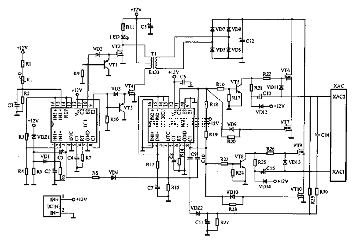
For users interested in multi-band operation, the circuit's design allows for easy modification of the inductor values. By incorporating switches or relays, users can quickly adapt the circuit to operate efficiently across different frequency bands, making this antenna amplifier a versatile solution for AM radio applications.The antenna amplifier circuit has a part count of about 40, using the following active parts: 2 NPN transistors (BC548`s), 1 MOSFET (BF981), 2 Varicap diodes (KV1235), as well as a 6v2 zener-diode. there is and a 330uH (micro Henry) inductor / coil, which can be modified for operation on other frequency bands.
Designed to work with a telescopic wh ip antenna, the amplifier circuit operates in the typical AM / MediumWave band of 550 - 1650 kHz (kilohertz), with a power requirement of 12 Volts DC. The circuit also has a gain control feature, so weather signals can be amplifier more, if need be. This amplification alteration is provided via, RV1 The amplifier circuit`s output impedance is 50 Ohms, which is the standard for all of radio receivers, so it ought to work well along with your AM receiver.
This circuit is designed to amplify the input from a telescopic whip antenna. The preamplifier is designed to cover the medium waveband from about 550Khz to 1650Khz. The tuning voltage is supplied via RV2, a 10k potentiometer connected to the 12 Volt power supply. RV1 is the gain control allowing weak signals to be amplified or strong signals to be attenuated. The control voltage is applied to gate 2 of TR1, a dual-gate MOSFET, the signal voltage applied via gate 1; the input signal being double tuned via the 330uH coil and the two KV1235 varicap diodes at the MOSFET`s input and by the same components at the BF981 MOSFET`s drain terminal. Both tuned circuits provide high selectivity across the entire tuning range. To aid stability the MOSFET stage is fed from a 6. 2V zener stabilized supply. To drive low impedance (50 ohm) receivers, the medium output impedance of the BF981 stage is enhanced by the composite amplifier made from Q2 and Q3.
Q2 is operating in common emitter boosting voltage levels by just over 2, Q3 is operating in emitter follower providing the circuit with low output impedance. Finally this active antenna can be used on other bands by changing the values of the 330uH coils. To perform on multiple bands switches or relays can be used to change the value of the coils. 🔗 External reference
Related Circuits
This circuit is a motion detection sensor that utilizes a light source and detector as an infrared motion detector. The motion sensor employs an infrared LED and a phototransistor. Since it relies on light, the sensor's sensitivity can be...
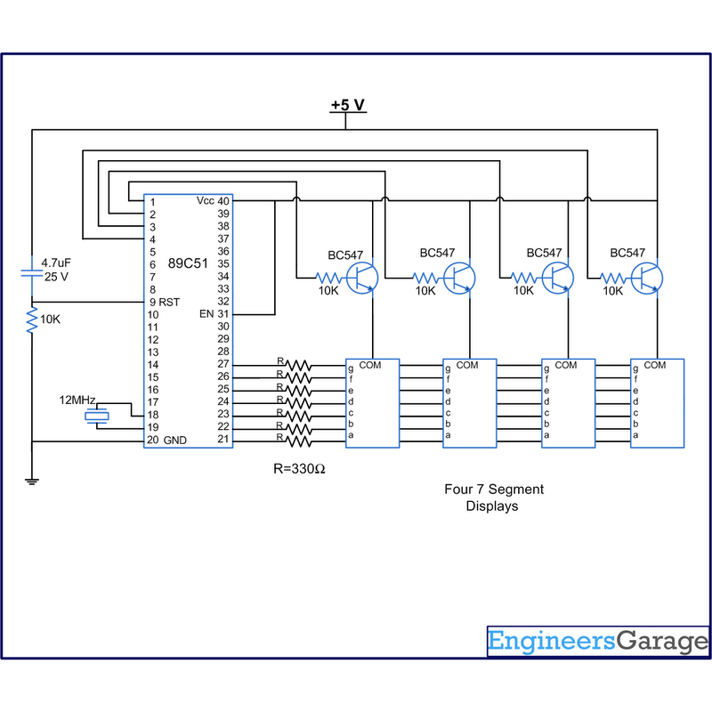
A digital clock displays time in a digital format. The circuit outlined here shows the time with double-digit minutes and two digits for seconds across four seven-segment displays. The segments of the displays are interconnected with the 8051 microcontroller...
The bicore is the basis of advanced BEAM. Most intermediate to advanced BEAM robots are built off of the bicore. Uses go all the way from photovores to servo motor drivers to walkers. What it is is basically just...
A common car inverter circuit and its working principle. Car inverter specifications include: Input voltage: DC 10V to 14.5V; Output voltage: AC 200V to 220V with a tolerance of 10%; Output frequency: 50Hz with a tolerance of 5%; Output...
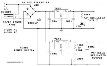
The circuit utilizes the 7805 voltage regulator, which features three connections: input, output, and ground. It delivers a fixed output voltage, with the last two digits of the part number indicating the specific output voltage, such as 05, 06,...
The DTMF codec stands for dual-tone multi-frequency codec. The multiple-channel infrared remote control switch circuit that incorporates the DTMF is depicted in the figure. It consists of an infrared remote control signal emitter, an infrared receiving signal amplifier, a...
Warning: include(partials/cookie-banner.php): Failed to open stream: Permission denied in /var/www/html/nextgr/view-circuit.php on line 713
Warning: include(): Failed opening 'partials/cookie-banner.php' for inclusion (include_path='.:/usr/share/php') in /var/www/html/nextgr/view-circuit.php on line 713