
Video Preamp Circuit
The NE592 and LM733 are integrated circuits designed for high-speed applications, making them suitable for video amplification tasks. In this configuration, the amplifier is set up to provide two outputs, J2 and J3, which are 180 degrees out of phase with each other. This anti-phase output configuration is beneficial for differential signaling and can help reduce noise and improve signal integrity in video applications.
The gain control resistor, R2, allows for adjustment of the amplifier's gain, enabling the user to optimize the output level based on the input signal strength and the requirements of the subsequent circuitry. This flexibility is essential in video applications where signal levels can vary significantly.
With a bandwidth of approximately 100 MHz, the circuit is capable of handling high-frequency signals, ensuring minimal signal degradation across the frequency spectrum typically encountered in video signals. This characteristic is crucial for maintaining the quality and clarity of the video output, particularly in high-resolution applications.
Overall, this schematic represents a robust solution for video amplification, leveraging the high-speed capabilities of the NE592 or LM733 to deliver reliable performance in various electronic systems.An NE592 or LM733 is used as a general-purpose video amplifier in this schematic.J2 and J3 provide two anti-phase outputs.R2 is a gain control.The bandwidth is about 100 MHz 🔗 External reference
Related Circuits

The circuit operates by processing an input signal through IC1-1 and a fourth-order low-pass filter, which provides a slope of 24 dB/octave with a cutoff frequency (fc) of 70 Hz and an amplification of 8.2 dB. The output from...
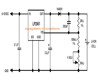
Unlike lead-acid batteries, one advantage of lithium-ion (Li-Ion) batteries is that they can be charged at a 1C rate initially. This means the charging current can be as high as the rated ampere-hour (AH) capacity of the battery at...
A schematic diagram for a broadband QRP SWR metering circuit intended for use in a QRP antenna tuner. The circuit allows the user to press a momentary DPDT switch to observe an LED indicator while adjusting the capacitors of...
A fluorescent tube is connected in an LC resonant circuit consisting of inductor L2 and capacitor C9. The bidirectional breakdown diode VD4 initiates the starting circuit. When AC power is applied, the gate potential of transistor VT2 increases due...
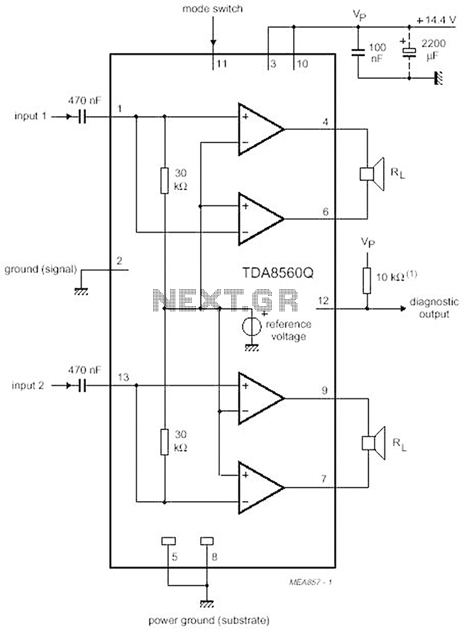
The proposed scheme is straightforward, requiring only a few external electronic components, making it suitable for car audio construction. The output power ranges from 2 to 4 Ohms, providing 2 x 30 W (with a maximum of 2 x...
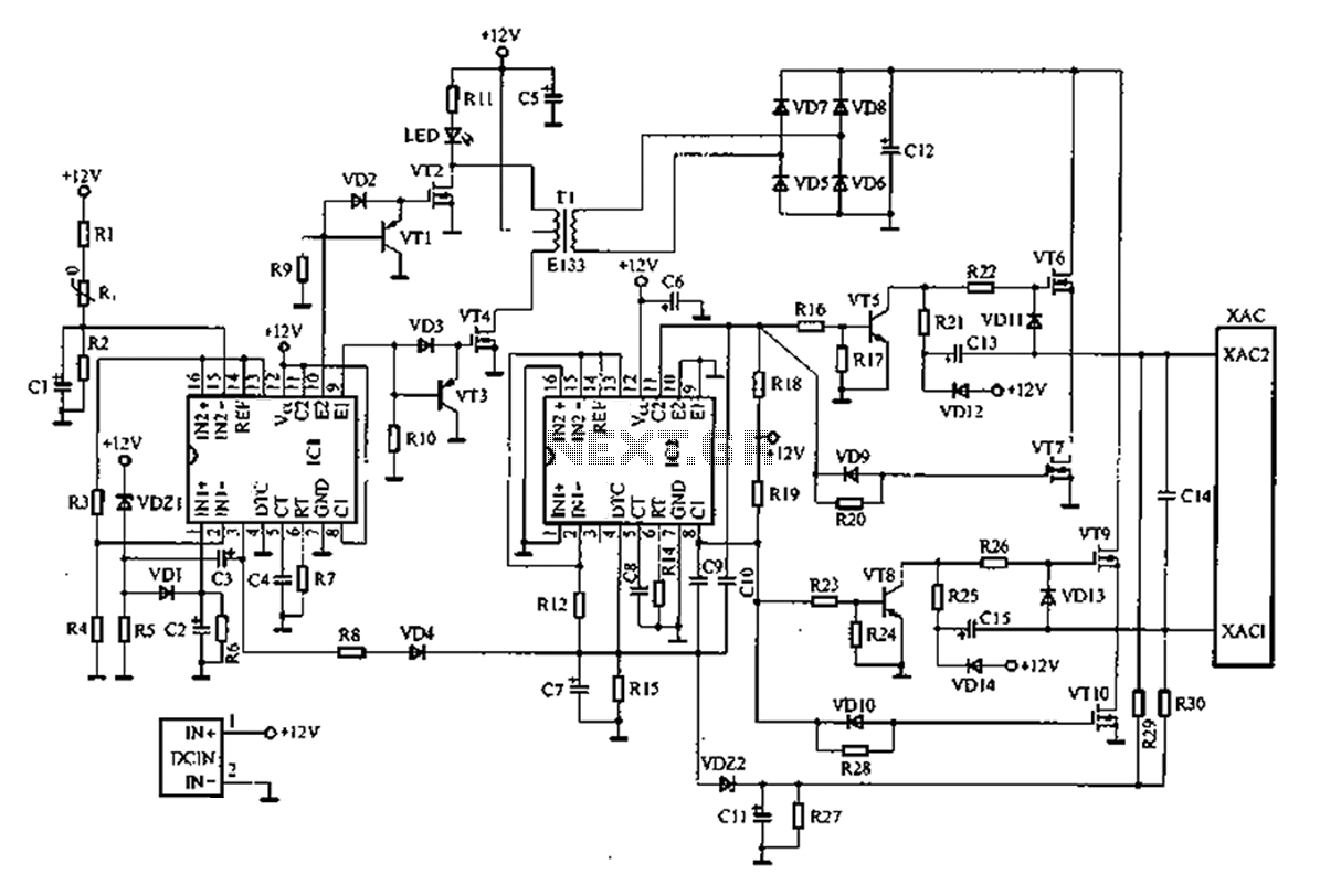
A common car inverter circuit and its working principle. Car inverter specifications include: Input voltage: DC 10V to 14.5V; Output voltage: AC 200V to 220V with a tolerance of 10%; Output frequency: 50Hz with a tolerance of 5%; Output...