
audio visual ringer circuit diagram
The circuit design for the additional telephone ringer is straightforward and effective, providing both auditory and visual notifications for incoming calls. The integration of the BA8204 or ML8204 IC simplifies the design, as it minimizes the number of required external components, thereby enhancing reliability and reducing assembly complexity. The use of a diode bridge for rectification ensures that the AC ringing signal is converted to a usable DC voltage, which is essential for powering the audio output stage.
Resistor R1 serves as a current limiter for the LED indicator, ensuring that it operates within safe limits while providing a clear visual alert. The combination of capacitors C1 and C2 in conjunction with the diode bridge allows for effective smoothing of the rectified signal, which is crucial for stable operation of the audio ringer.
The audio output, which is modulated by the adjustable resistors R3, R4, and R5, allows for customization of both the sensitivity and frequency characteristics of the ringer. This feature is particularly beneficial in environments where varying levels of ambient noise may affect the audibility of the ringer. The piezo-ceramic sound generator is chosen for its high efficiency and compact size, making it suitable for integration into various settings.
In summary, this additional telephone ringer circuit offers a practical solution for enhancing notification of incoming calls in separate rooms, with the flexibility for users to tailor the sound output to their preferences. Careful selection of component values and configuration allows for a versatile design that meets the needs of diverse applications.Many a times one needs an ex- tra telephone ringer in an ad- joining room to know if there is an incoming call. For example, if the telephone is installed in the drawing room you may need an extra ringer in the bedroom.
All that needs to be done is to connect the given circuit in parallel with the existing telephone lines using twin flexible wires . This circuit does not require any external power source for its operation. The section comprising resistor R1 and diodes D5 and LED1 provides a visual indication of the ring. Remaining part of the circuit is the audio ringer based on IC1 (BA8204 or ML8204). This integrated circuit, specially designed for telec- om application as bell sound generator, requires very few external parts. It is readily available in 8-pin mini DIP pack. Resistor R3 is used for bell sensitivity adjustment. The bell frequency is controlled by resistor R5 and capacitor C4, and the repeat frequency is controlled by resistor R4 and capacitor C3.
A little experimentation with the various values of the resistors and capacitors may be carried out to obtain desired pleasing tone. Working of the circuit is quite simple. The bell signal, approximately 75V AC, passes through capacitor C1 and resistor R2 and appears across the diode bridge comprising diodes D1 to D4.
The rectified DC output is smoothed by capacitor C2. The dual-tone ring signal is output from pin 8 of IC1 and its volume is adjusted by volume control VR1. Thereafter, it is impressed on the piezo-ceramic sound generator Disclaimer: All the information present on this site are for personal use only.
No commercial use is permitted without the prior permission from authors of this website. All content on this site is provided as is and without any guarantee on any kind, implied or otherwise. We cannot be held responsible for any errors, omissions, or damages arising out of use of information available on this web site.
The content in this site may contain COPYRIGHTED information and should not be reproduced in any way without prior permission from the authors. 🔗 External reference
Related Circuits
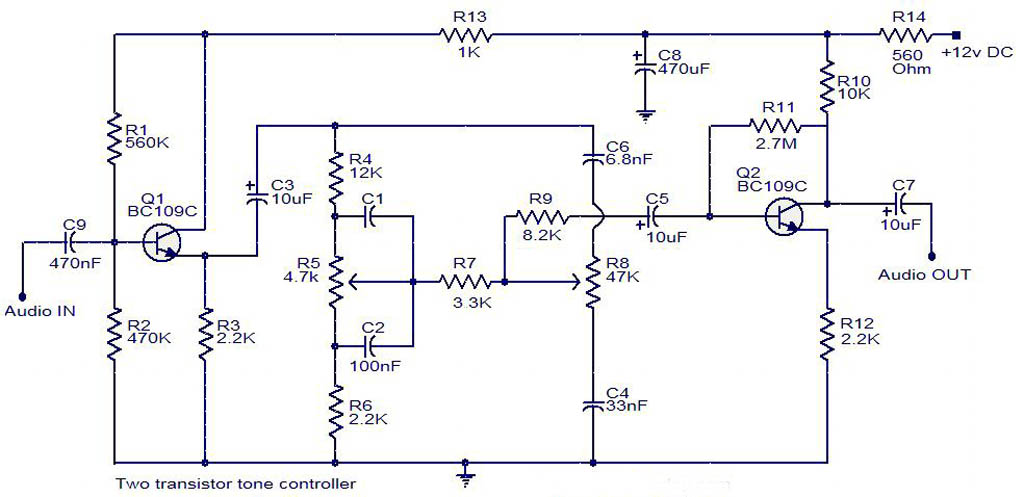
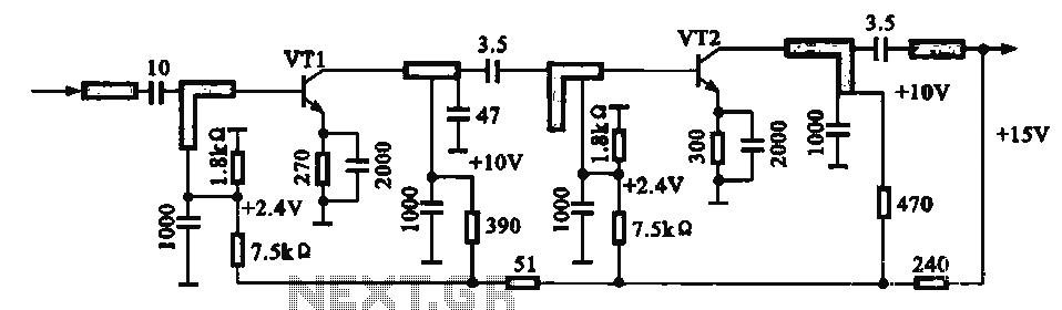
The electrical schematic diagram presented below illustrates a simple two-transistor tone controller audio circuit, which is available for free download. This circuit is based on the well-known Baxandall tone control design. Variations in the values of the transistor components...

This shadow alarm circuit can detect a moving shadow in a confined area, providing protection against theft. When an individual approaches the unit, it triggers a loud alarm to deter the theft attempt. The circuit leverages the light-sensing characteristics...

This NiCd battery charger circuit schematic can charge 6 volts as well as 12 volts NiCad batteries. It uses a transformer that can deliver 4 to 5 A current. The NiCd battery charger circuit is designed to accommodate both 6V...

The individual has been engaged in garden railroading for just over a year, utilizing skills from various hobbies. They have designed and built two scratch-built bridges and nearly 100 trestle bents to support a 200-foot main line. Their interests...
An IF pre-amplifier circuit is presented in a distributed-parameter microstrip configuration. It operates within the frequency range of 950 to 1,470 MHz. The output impedance is approximately 75 ohms. The power supply for the circuit is connected to the...

This circuit is designed for a project utilizing a 6V, 400 mA DC power supply. The open-circuit voltage is specified, indicating the voltage measured when no load is connected. The circuit employs a regulated 6V power supply, which is essential...