


Ujt-battery-charger
#UJT
#SCR
#relaxation oscillator
#battery charging
#current control
#polarity protection
#trigger circuit
#automated charging
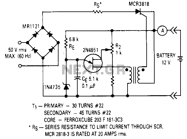
Description: This circuit will not function unless the battery to be charged is connected with the correct polarity. The voltage of the battery regulates the charger, and when the battery is fully charged, the charger will stop supplying current to it. The charging current for the battery is provided through the SCR, which is triggered into the conducting state by the UJT relaxation oscillator. The oscillator activates only when the battery voltage is low. V8281 of the UJT is derived from the voltage of the battery being charged, and since Vp equals Vn equals V8281, a higher V8281 results in a higher Vp. When Vp exceeds the breakdown voltage of the zener diode Z1, the UJT will stop firing, and the SCR will cease conduction. This indicates that the battery has reached its desired charge level as determined by R2.
The described circuit functions as a battery charger utilizing a Unijunction Transistor (UJT) oscillator and a Silicon Controlled Rectifier (SCR) for controlling the charging process. The circuit is designed to ensure that the battery is charged correctly and safely, with built-in safeguards against overcharging.
At the heart of the circuit is the UJT relaxation oscillator, which generates a pulse signal that triggers the SCR. The oscillator is designed to activate only when the battery voltage drops below a certain threshold, ensuring that charging occurs only when necessary. The voltage across the battery (denoted as V8281) directly influences the operation of the UJT. As the battery voltage rises, Vp (the peak voltage of the UJT) also increases, leading to a situation where Vp can reach a critical level.
When Vp surpasses the breakdown voltage of the zener diode Z1, this condition effectively disables the UJT from firing. As a result, the SCR is no longer triggered, halting the current flow to the battery. This mechanism provides a reliable method for preventing overcharging, as the battery will only receive current until it reaches the charge level set by the resistor R2, which is part of the circuit's feedback loop.
In summary, the circuit employs a combination of a UJT oscillator and an SCR to manage the battery charging process, ensuring that the battery is charged efficiently and safely while preventing overcharging through voltage regulation and feedback mechanisms.This circuit will not work unless the battery to be charged is connected with proper polarity. The battery voltage controls the charger and when the battery is fully charged, the charger will not supply current to the battery. The battery charging the current is obtained through the SCR when it is triggered into the conducting state by the UJT relaxation oscillator.
The oscillator is only activated when the battery voltage is low. V8281 of the UJT is derived from the voltage of the battery to be charged, and since Vp= Vn= V8281 ; the higher V828" the higher Vp. When Vp exceeds the breakdown voltage of the zener diode Zl, the UJT will cease to fire and the SCR will not conduct.
This indicates that the battery has attained its desired charge as set by R2.
The described circuit functions as a battery charger utilizing a Unijunction Transistor (UJT) oscillator and a Silicon Controlled Rectifier (SCR) for controlling the charging process. The circuit is designed to ensure that the battery is charged correctly and safely, with built-in safeguards against overcharging.
At the heart of the circuit is the UJT relaxation oscillator, which generates a pulse signal that triggers the SCR. The oscillator is designed to activate only when the battery voltage drops below a certain threshold, ensuring that charging occurs only when necessary. The voltage across the battery (denoted as V8281) directly influences the operation of the UJT. As the battery voltage rises, Vp (the peak voltage of the UJT) also increases, leading to a situation where Vp can reach a critical level.
When Vp surpasses the breakdown voltage of the zener diode Z1, this condition effectively disables the UJT from firing. As a result, the SCR is no longer triggered, halting the current flow to the battery. This mechanism provides a reliable method for preventing overcharging, as the battery will only receive current until it reaches the charge level set by the resistor R2, which is part of the circuit's feedback loop.
In summary, the circuit employs a combination of a UJT oscillator and an SCR to manage the battery charging process, ensuring that the battery is charged efficiently and safely while preventing overcharging through voltage regulation and feedback mechanisms.This circuit will not work unless the battery to be charged is connected with proper polarity. The battery voltage controls the charger and when the battery is fully charged, the charger will not supply current to the battery. The battery charging the current is obtained through the SCR when it is triggered into the conducting state by the UJT relaxation oscillator.
The oscillator is only activated when the battery voltage is low. V8281 of the UJT is derived from the voltage of the battery to be charged, and since Vp= Vn= V8281 ; the higher V828" the higher Vp. When Vp exceeds the breakdown voltage of the zener diode Zl, the UJT will cease to fire and the SCR will not conduct.
This indicates that the battery has attained its desired charge as set by R2.
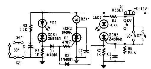
scr high power alarm driver circuit design
A straightforward high-power alarm driver electronic project can be developed using this circuit diagram. This high-power alarm driver project utilizes a low-power SCR to trigger a high-power SCR. When switches S2, S3, or S4 are opened or switches S5, S6,...
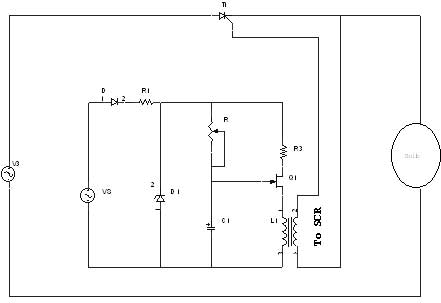
ujt triggering circuit
A unijunction transistor (UJT) is an electronic semiconductor device characterized by a single junction. It consists of three terminals: an emitter (E) and two bases (B1 and B2). The base is constructed from a lightly doped n-type silicon bar, with...
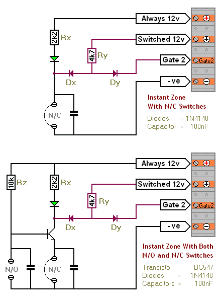
An SCR Based Burglar Alarm - Adding Extra Zones
The SCR Burglar Alarm System allows for the addition of multiple extra zones. The primary circuit is designed for typical normally-closed input devices, including magnetic reed contacts, micro switches, foil tape, and passive infrared (PIR) sensors. An additional circuit includes...
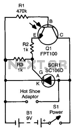
Slave Flash Trigger
The SCR is connected across the trigger circuit of the flash gun. In its default state, the SCR remains off, allowing the flash gun to charge to its trigger voltage. A phototransistor, Q1, is utilized to monitor the light level....
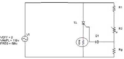
triggering circuit
Simple resistor and diode combinations are used to trigger and control silicon-controlled rectifiers (SCRs) across the full 180-degree electrical range, exhibiting reliable performance at commercial temperatures. These circuits function optimally when SCRs possess relatively high gate sensitivities. In this configuration,...
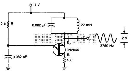
Oscillator produces audio sinusoids
A tuned circuit can be incorporated into the current-pulse path of a UJT oscillator to generate a 3750-Hz sinusoidal signal at output B2, using the specified component values.
The UJT (Unijunction Transistor) oscillator is a type of relaxation oscillator that utilizes...
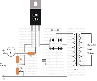
how to make inexpensive current
Charging any type of rechargeable battery is critical and requires attention, particularly regarding the current or rate at which the battery is charged. This factor is essential for maintaining the battery's lifespan and efficiency over time. The circuit diagram presented...
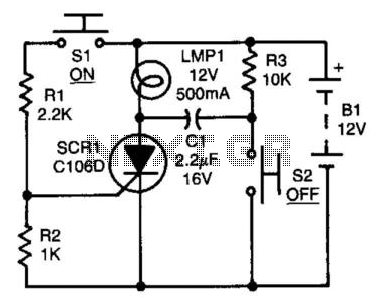
Scr Capacitor Turn-Off Circuit
After the SCR is activated, capacitor CI charges up to nearly the full supply voltage through resistor R3 and the anode of the SCR. When switch S2 is later closed, it grounds the positive terminal of CI, causing the charge...
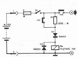
Safety polarity connection circuit
Safety polarity connection circuit design using common electronic components
The safety polarity connection circuit is designed to ensure that electronic devices are connected with the correct polarity, preventing damage from reversed connections. This circuit typically employs common electronic components such as...