
electronic timer with display circuit

The circuit employs the ICM7217, a versatile integrated circuit designed for digital timekeeping applications. The CMOS architecture allows for low power consumption and reliable operation. The four-digit display outputs the time in either minutes or seconds, depending on the configuration selected via switch S4.
The clock generator, IC3, is critical for providing a consistent timing reference, operating at a one-second interval. This clock signal can be further processed by IC4, which divides the frequency for applications that require longer time intervals, such as timing events that exceed one hour. The reset function is implemented through the combination of R9 and C5, ensuring that the circuit initializes correctly whenever power is applied.
The configuration of switches S7 to S10 allows for user interaction with the display, enabling the setting of countdown values. The ability to store and adjust these values enhances the circuit's functionality, making it suitable for various timing applications. The countdown feature is initiated by switch S2, which triggers the ICM7217C to decrement the displayed value. The buzzer serves as an alert mechanism, providing an audible signal when the countdown reaches the predetermined threshold of 20.00, thus signaling the completion of the timing cycle.
Overall, this circuit design showcases an efficient use of integrated circuits and user interface components to create a practical and user-friendly timing solution.The circuit is built using ICM7217 integrated circuit, manufactured by Intersil, which contains a CMOS counter up / down, with 4 digits and display properly. IC3 is the clock generator circuit which provides a square wave with period 1 s clock signal is available on pin 3 (Q13).
It can be divided by 60 in IC4, if necessary, measurement of longer t han one hour. When S6 is closed, power is connected and IC1 is reset by R9 and C5. S4`s position determine if minutes or seconds are counted: not exceeding 59 h and 59 min (position 2) or 59 min and 59 s (position 1). Miniature switches S10 S7 adjusts the display to indicate 20. 00. In a short press of S3, this choice is stored by IC1. After that, S7-S10 is adjusted so that the display to indicate 35. 00. Meanwhile, S1 must be open. Pressing S2 cause of integrative ICM7217C start counting backwards, starting from 35. 00. When the display shows 20. 00, buzzer sounds shorter. 🔗 External reference
Related Circuits
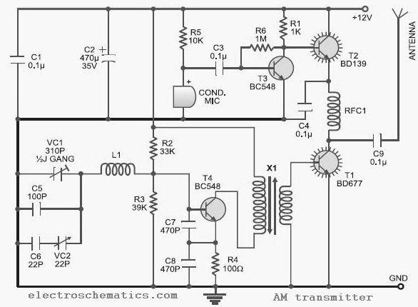
This low-cost AM transmitter is tunable from 10 to 15 MHz with the assistance of a ½J gang condenser VC1, which sets the carrier frequency of the amplitude modulation transmitter in conjunction with inductor L1. Frequency trimming can be...
The PWM circuit is causing the inverter's current consumption to reach a dangerous level of 14 Amps. A potential solution involves reducing the drive voltage to the gates of the MOSFETs by controlling the base voltage of the buffer...
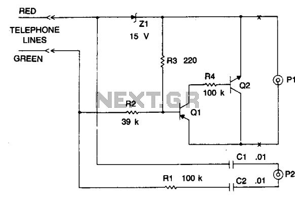
The device is a DC switch that remains normally on due to the forward biasing of Q1 through resistor R3. Q1 clamps Q2 into a forward state by biasing its complementary transistor well into saturation via resistor R4. The...
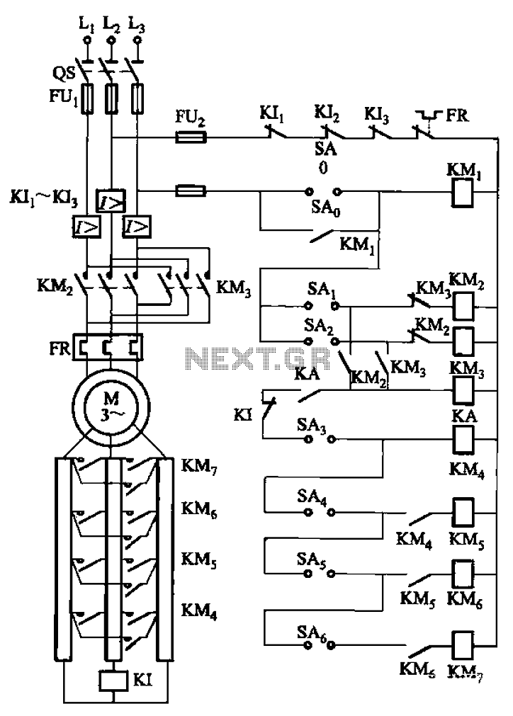
The circuit depicted in Figure 3-168 utilizes a controller for speed grading and reversing control. A reverse brake is connected to the rotor circuit through an overcurrent relay, labeled KI, for control. The current relay KIi to KI3 serves...
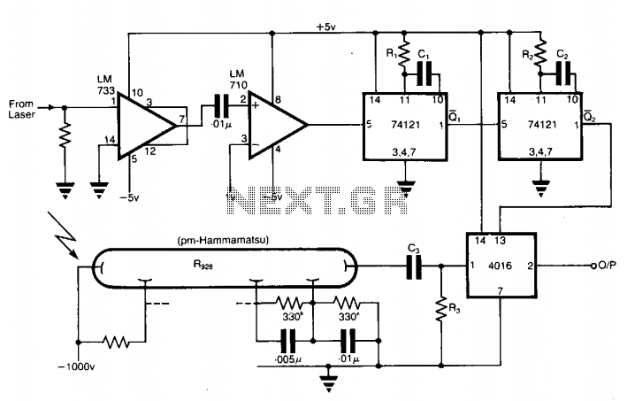
The application involves observing the light pulse emerging from a thick specimen after transillumination by a laser pulse. Pulses derived from the laser source are amplified using a Video Amplifier LM733. The reference level is set to 1 V...
The digital lock shown below uses 4 common logic ICs to allow controlling a relay by entering a 4 digit number on a keypad. The first 4 outputs from the CD4017 decade counter (pins 3,2,4,7) are gated together with...