

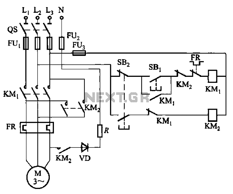

Seven one-way operation of the dynamic braking circuit
Circuit shown in Figure 3-139. This circuit uses a rectifier diode rectifier brake for neutral grounding of the three-phase four-wire power supply system. ...
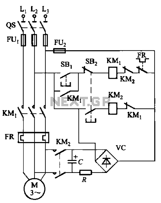
Six-way operation of the dynamic braking circuit
Circuit shown in Figure 3-138. The line is also using the principle of energy storage capacitors discharge achieve braking. Capacitance C and resistance R para...
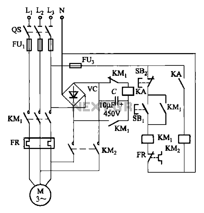
Five-way operation of the dynamic braking circuit
Circuit shown in Figure 3-137. This eliminates the need for a step-down transformer line, using the principle of energy storage capacitor discharge realization...
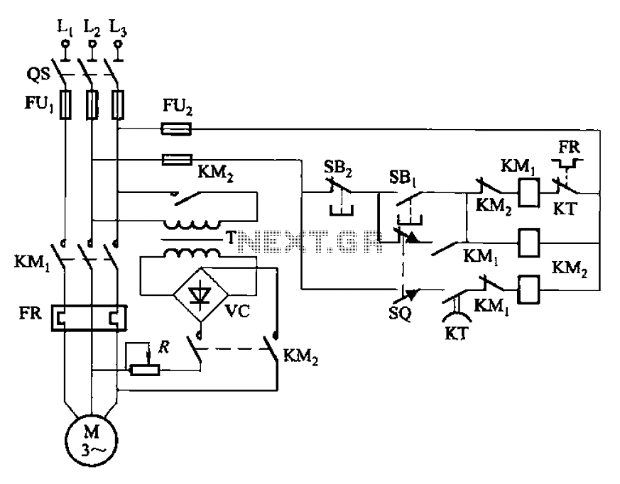
Four-way operation of the dynamic braking circuit
Circuit shown in Figure 3-136. The line adds a limit switch SQ, when the motor is running with a mechanical device to a predetermined position, turn off the po...
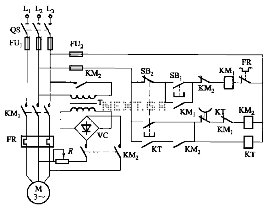
Three-way operation of the dynamic braking circuit
Circuit shown in Figure 3-135. Braking time is determined by the time relay KT. ...
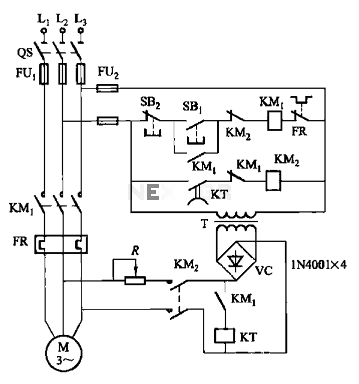
Way operation dynamic braking circuit 2
Circuit shown in Figure 3-134. This circuit uses automatic control braking means, it is given in Figure 3-133 (a) a base improvements made on the basis of usin...
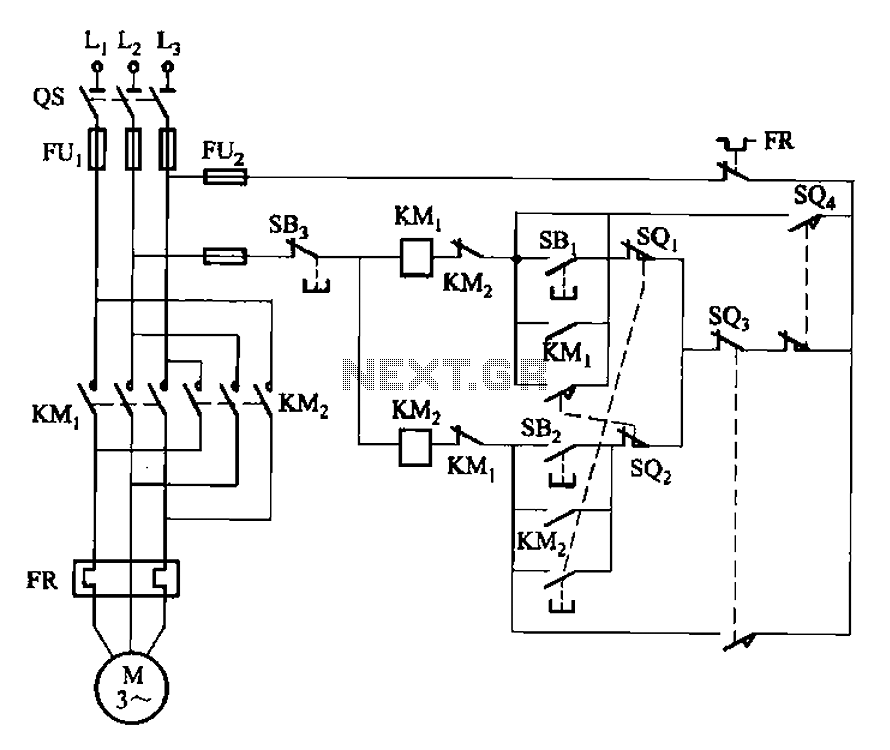
Five reversing operation of the reverse brake circuit
Circuit shown in Figure 3-132. The line is automatically round-trip, plug braking circuit. In order to prevent or limit switch SQl offside SQz malfunction caus...
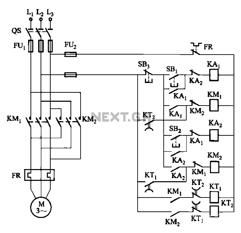
Four reversing operation of the reverse brake circuit
Circuit shown in Figure 3-131. It uses a relay in place of the speed control relay. The circuit is suitable for dusty rings and other poor environmental situat...
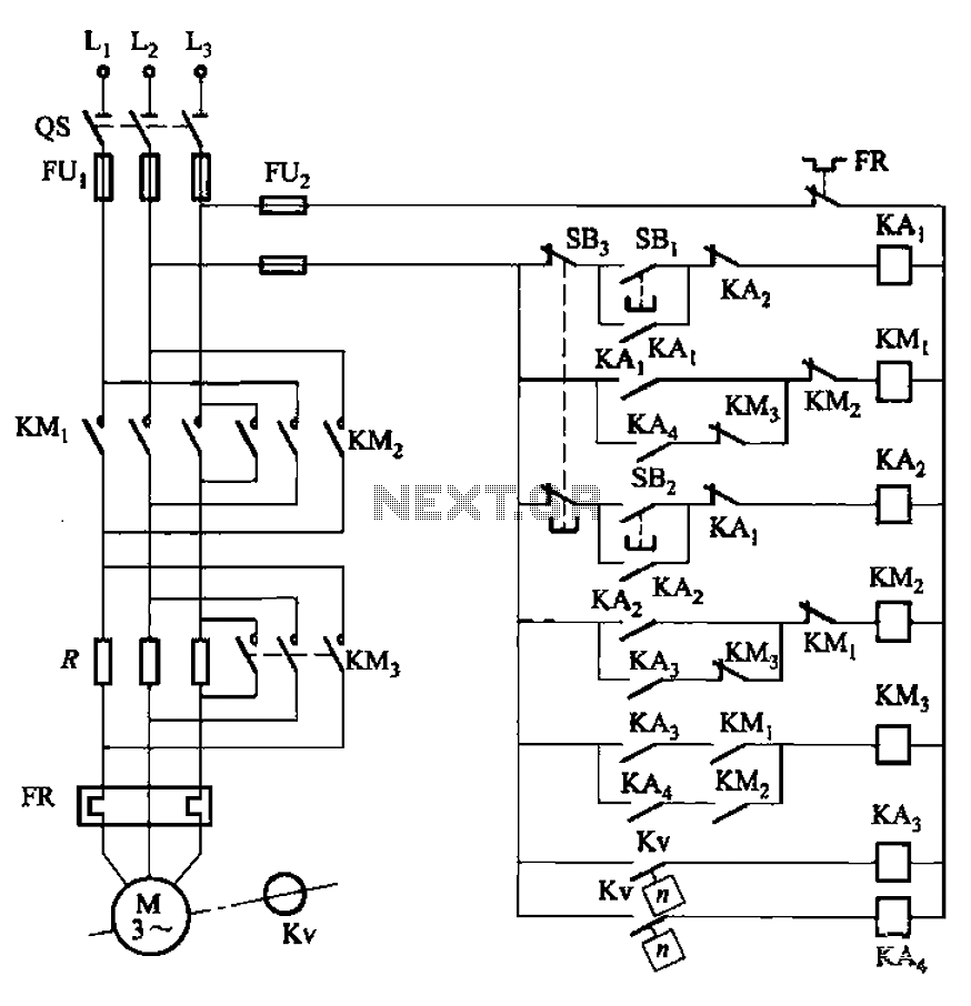
Three reversing operation of the reverse brake circuit
Circuit shown in Figure 3-130. The line differs from FIG 3-129 line that press the stop button SB3, the electric motor begins braking. In addition, start-up an...
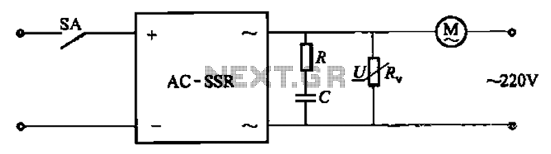
Solid state relay circuit controls the motor-way operation
Circuit shown in Figure 3-13. Figure, RC surge absorption circuit is, R, zinc oxide varistors (such as MY31 type, MYH12 type, MYH20 type, etc.), an overvoltage...
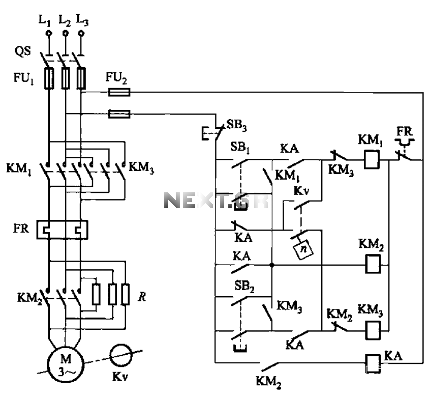
Reversing the operation of the two reverse brake circuit
Circuit shown in Figure 3-129. The circuit is C650-2 lathe brake control circuit. Kv using speed control relay. ...
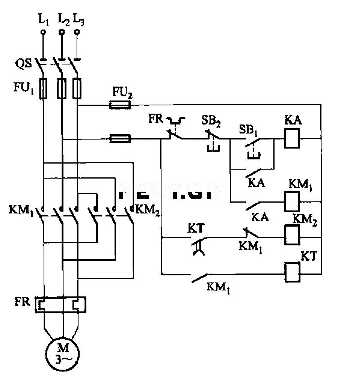
Four-way operation of the reverse brake circuit
Circuit shown in Figure 3-127. It uses the time relay KT instead of the speed relay. Plugging time determined by the KT set. Generally 1-2s (adjustable). The c...
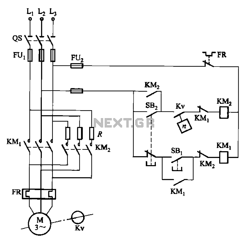
One-way operation of the brake circuit reverse
Circuit shown in Figure 3-124. The line does not use an intermediate relay. Figure, Kv is the speed relay, when the electric engine speed is greater than 120r/...
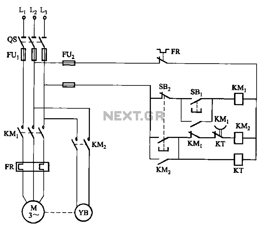
Before power is in the release state holding brake circuit
Circuit shown in Figure 3-123. When you press the stop button SBz, contact KMi release, cut off the power to the motor, at the same time, KMz pull, turn the el...
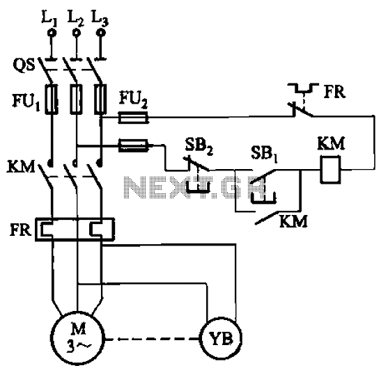
Before power is in the hold state holding brake one circuit
Circuit shown in Figure 3-121. The key component of electromagnetic holding brake is an electromagnetic brake brakes, brake solenoid which is mainly composed o...
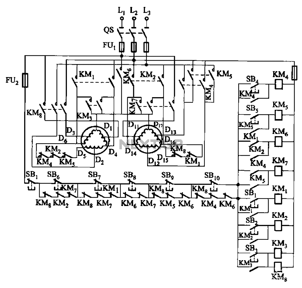
2Y-Y-2 - connection four-speed motor contactor control circuit
Circuit shown in Figure 3-120. If the motor capacity is small (less than the rated current 5A), it can use an intermediate relay (contact a few more) instead o...
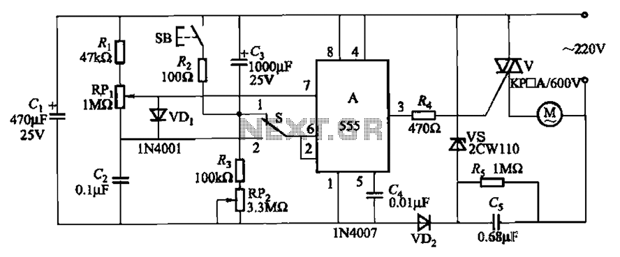
Three single-phase motor stepless thyristor circuits
Circuit shown in Figure 3-12. It has a variable speed and timing control functions. When the switch S placed in the 1 position, press the button SB, the motor ...
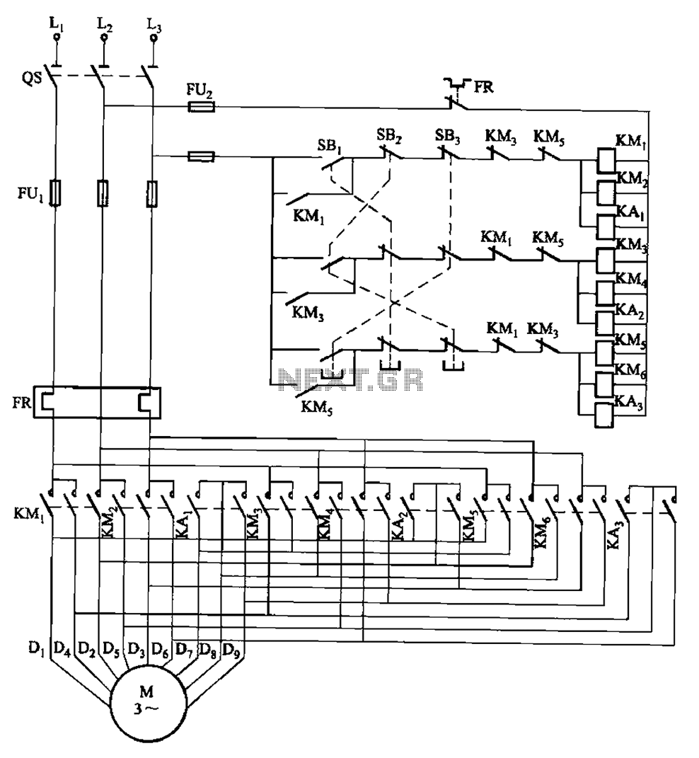
2Y-2Y-2Y-connected three-speed motor contactor control circuit
Circuit shown in Figure 3-115. It uses contactors and double buttons, so when converting speed without press stop press ugly, can be directly converted. SBi, S...
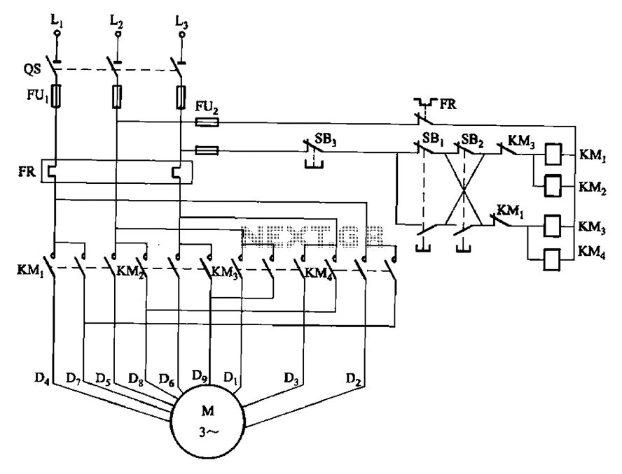
two-speed motor contactor control circuit two speeds in the same direction
Circuit shown in Figure 3-112. Figure, SBi as the first speed operation button, SBz is run by the second speed class. Two speeds in the same direction. ...
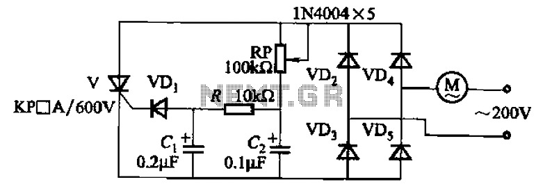
Single-phase motor stepless thyristor circuit 2
Circuit shown in Figure 3-11. It uses a one-way thyristor control. Adjustment potentiometer RP, continuously changing the motor speed. ...