

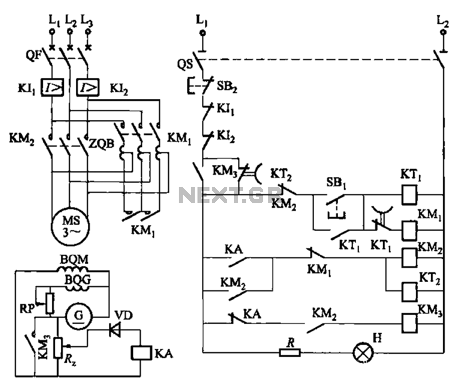

Step-down autotransformer rotor excitation frequency starting circuit
Circuit shown in Figure 3-187. When you start, then people start auto ZQB step-down transformer. After a period of delay, ZQB out of operation, the motor incre...
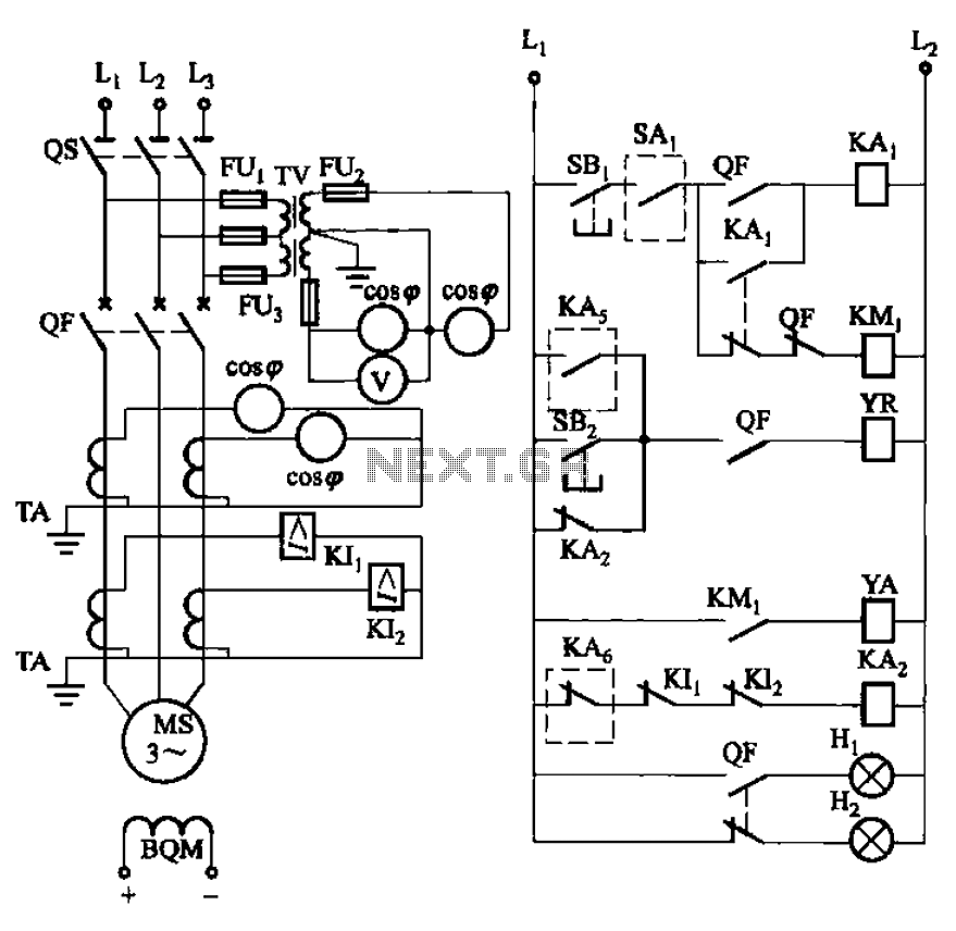
Synchronous motor full voltage start-up circuit
Circuit shown in Figure 3-186. Figure, os for the isolation switch; QF vacuum circuit breakers; YR line for the circuit breaker coil; YA circuit breaker closin...
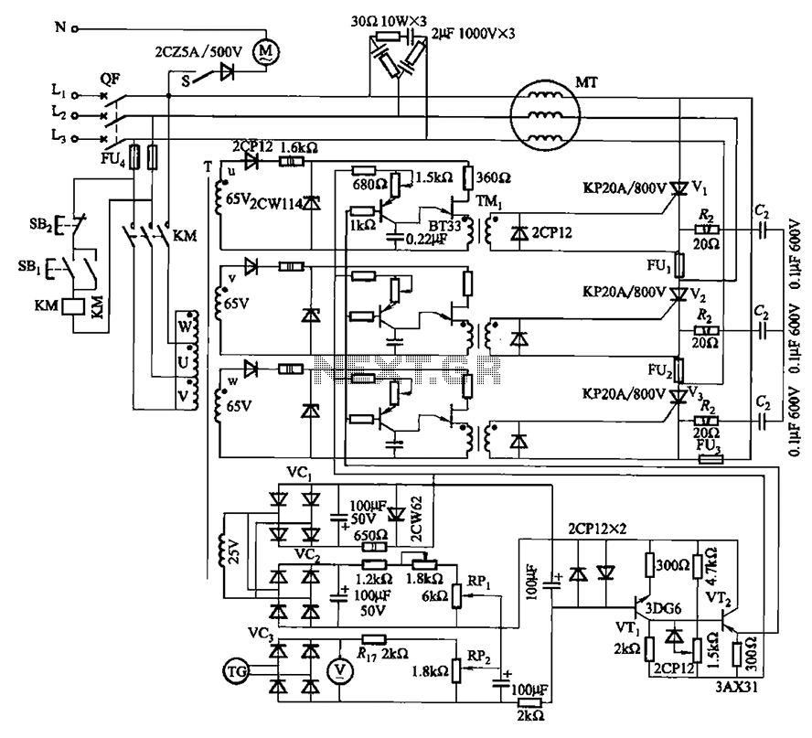
Thyristor AC torque motor speed control circuit 2
Circuit shown in Figure 3-181. Main circuit consists of three thyristor Vi-V3 components. Trigger circuit single-junction transistor relaxation oscillator. Spe...
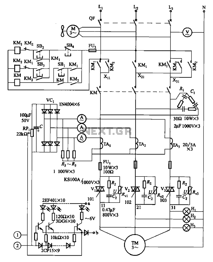
Two motor speed control circuit and the main level indicating circuit
Circuit shown in Figure 3-178. It withered speed torque motor for continuous casting machine, the circuit from the main circuit, trigger circuit, manual and au...
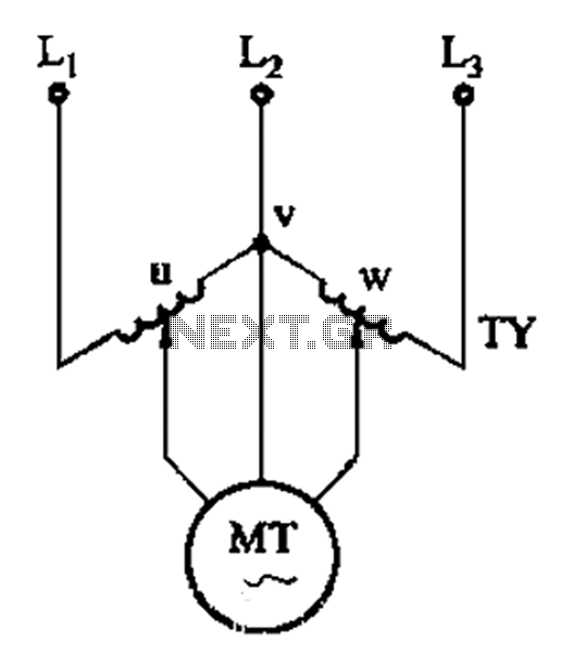
V-shaped torque motor speed control circuit
Circuit shown in Figure 3-177. It uses two single-phase voltage regulator and connected to a V-shaped, single-phase regulators when two concentric series of ti...
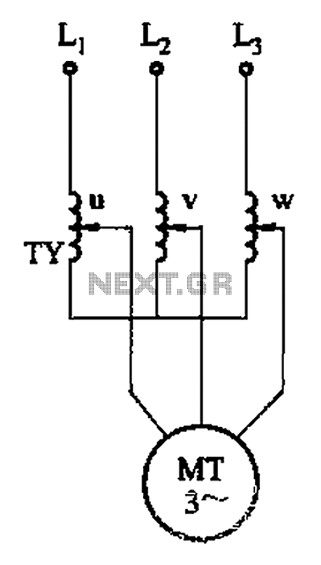
Three phase torque motor speed control circuit
Circuit shown in Figure 3-176. This adjustment method, the motor can run at equilibrium, adjustment range and relatively wide. But requires a three-phase volta...
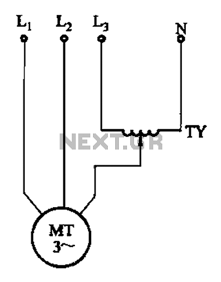
Single-phase torque motor speed control circuit 2
Circuit shown in Figure 3-175. Regulator connected between one phase and neutral. It applies to the rated voltage of 380V torque motor. This method than the de...
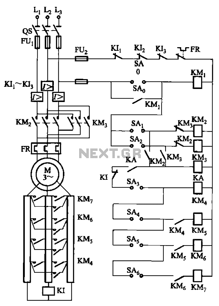
A control circuit reversing braking and reverse grading speed control function
Circuit shown in Figure 3-168, which uses the controller SA grading speed and reversing control; reverse brake connected to the rotor circuit overcurrent relay...
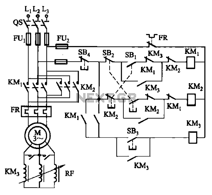
Frequency sensitive rheostat manually start reversing circuit
Circuit shown in Figure 3-166. It uses the button control. When start forward, press SB], the motor rotor string frequency sensitive people rheostat RF operati...
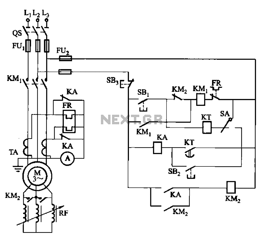
Frequency sensitive rheostat for manual and automatic way starting circuit
Circuit shown in Figure 3-164. The circuit can be manual and automatic two ways. During startup, KA normally closed contact relay FR hot heating element shorte...
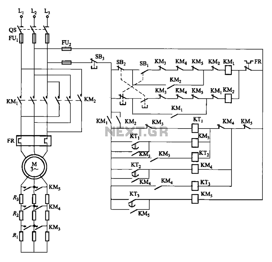
Time to start reversing relay control circuit
Circuit shown in Figure 3-162. in graph. SBi is forward the start button, SBz to reverse the start button, SB3 for the stop button. Start switching resistance ...
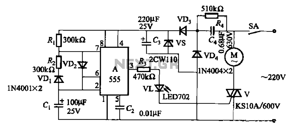
Single-phase motor automatic intermittent operation control circuit
Circuit shown in Figure 3-16. It uses 555 IC A as the control element; capacitive step-down circuit; bidirectional thyristor V between the motor control interm...
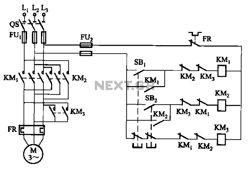
Forward and reverse running short brake circuit
Circuit shown in Figure 3-154. Figure, KM3 braking contactors. Shutdown, you can disconnect the os. At this time, KM3 was electric pull its normally open conta...
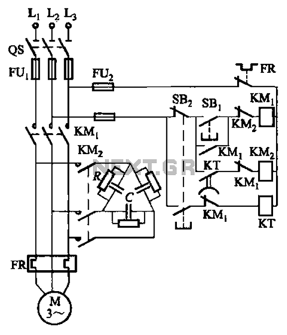
Single-speed motor excitation power from a braking circuit
Circuit shown in Figure 3-151. Figure 3-151 (a) of the capacitor banks connected into shape, it applies to shaped or Y-connected motor; Fig. 3-151 (b) of the Y...
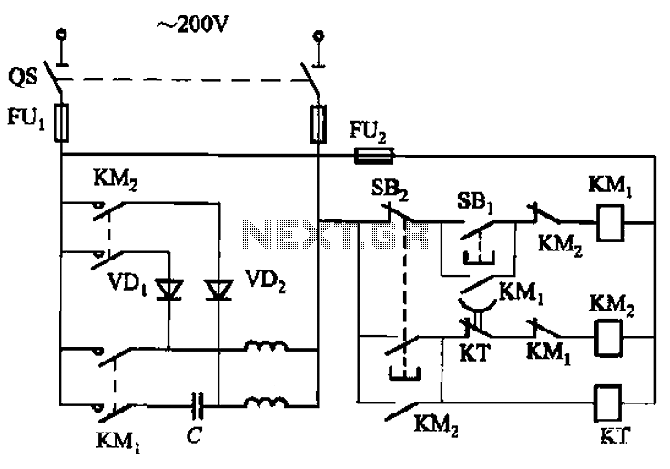
Single-phase motor energy consumption of the two brake circuits
Circuit shown in Figure 3-150. When shut down, the contactor KM1 released. KMz pull, 220V AC power supply through the diode VDi, VD2 rectifier, the motor prima...
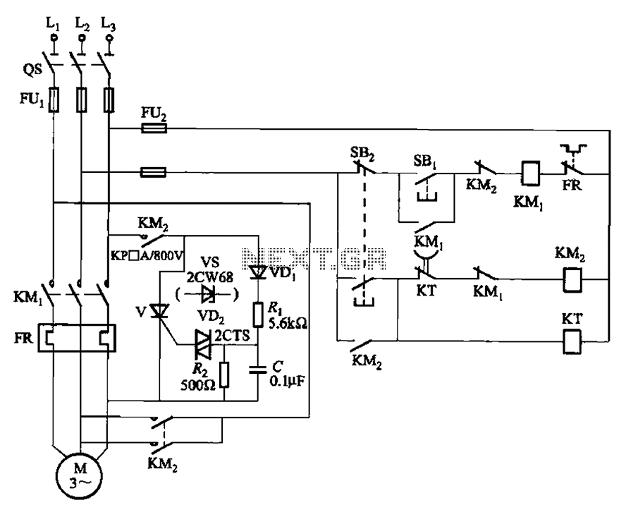
Dynamic braking circuit control thyristor
Circuit shown in Figure 3-148. The circuit eliminates the need for step-down transformer, using thyristor for brake control, for small capacity asynchronous mo...
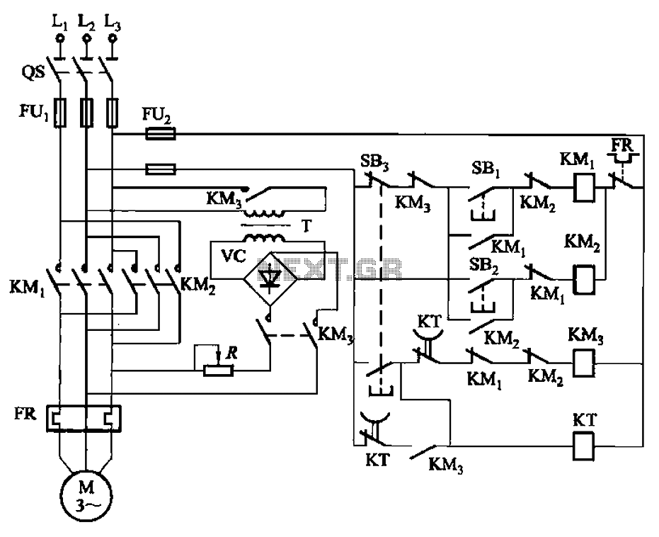
One of the positive and negative brake circuit to operate energy
Circuit shown in Figure 3-144. The circuit for the automatic control of dynamic braking circuit using the time relay KT control system up time, dynamic braking...
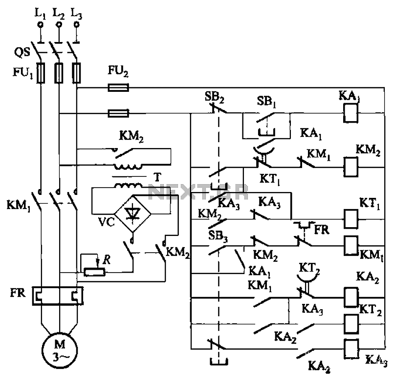
The brake a little dynamic braking circuit
Circuit shown in Figure 3-143. The line not only make the braking effect of the motor is in the normal shutdown, and jog through the process and has a good bra...
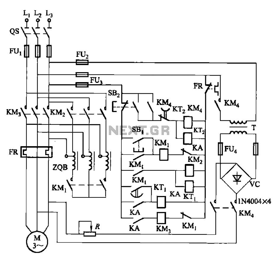
Nine one-way operation of the dynamic braking circuit
Circuit shown in Figure 3-141. The line autotransformer voltage starting, dynamic braking. Figure, SBi buck start button, SBz the stop button. Buck start-up ti...
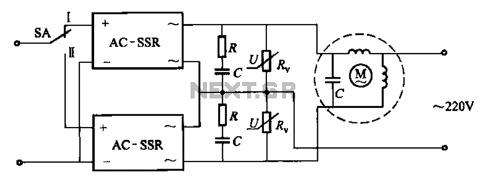
Solid-state relays control the motor forward and reverse operation circuit
Circuit shown in Figure 3-14. SA switch placed in the work position, the motor is transferred; SA placed bit is set, reverse the motor. Drawing, over-voltage p...