

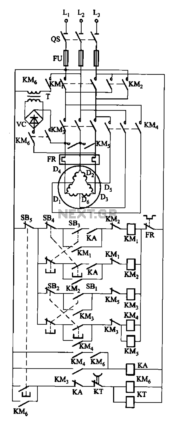

Dynamic braking with the two-speed motor reversing control circuit
Circuit shown in Figure 3-108. SB3 for the forward button; S Island reverse button; SBi as low start button; SB2 to speed the start button; SBs for the stop bu...
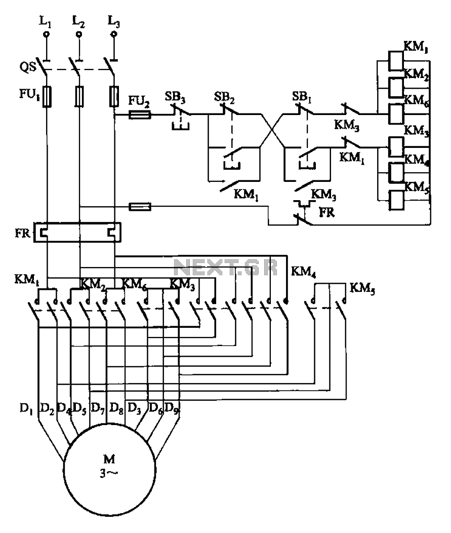
2Y-2Y connection two-speed motor contactor control circuit
Circuit shown in Figure 3-107. Figure, SBi is running at low speed button, SB2 for the high-speed operation button. ...
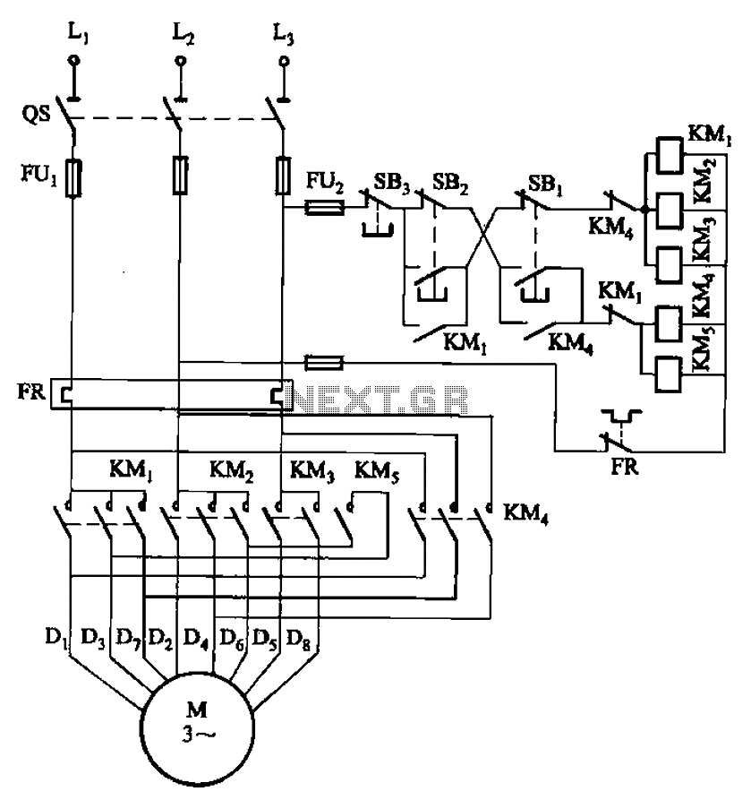
2 -Y-connected two-speed motor contactor control circuit
Circuit shown in Figure 3-104. in graph. SB2 is running at low speed button, SBi as the high-speed operation button. ...
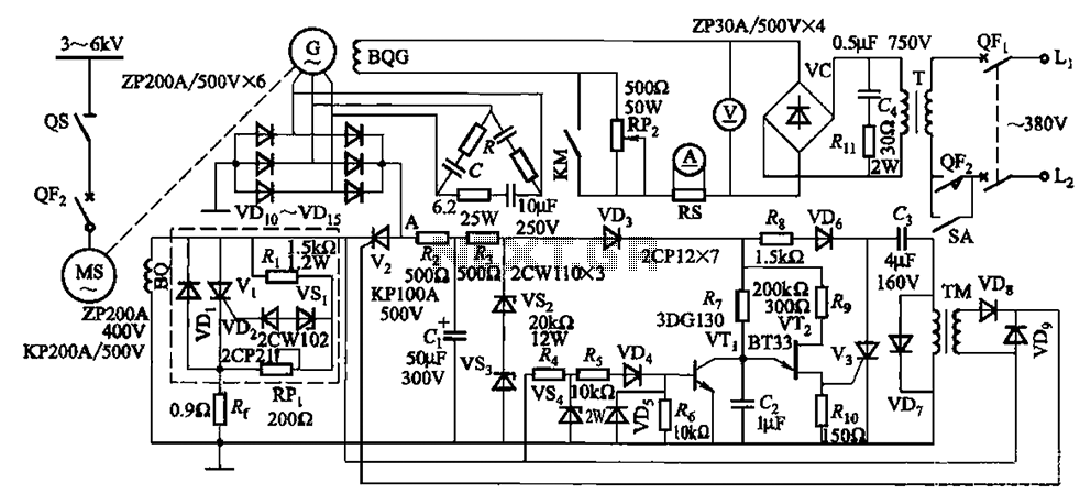
One synchronous motor thyristor excitation circuit
Circuit shown in Figure 16-105. Figure, MS synchronous motor. BQ its field winding; G AC excitation hair motors, BQG its field winding {empty box as part of th...
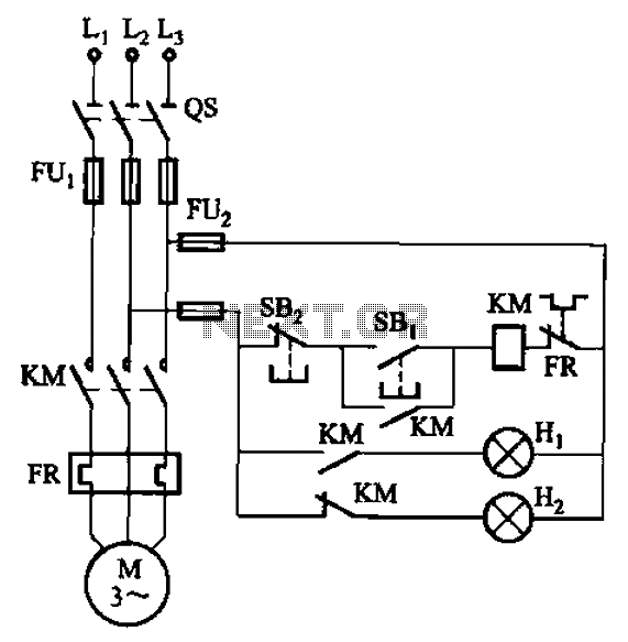
With self-locking function of the forward start circuit
Circuit shown in FIG. 3 + 20. Figure, SBi as the start button, SB2 is the stop button, Hi to run lights, Hz as down lights. In the circuit described later, in ...
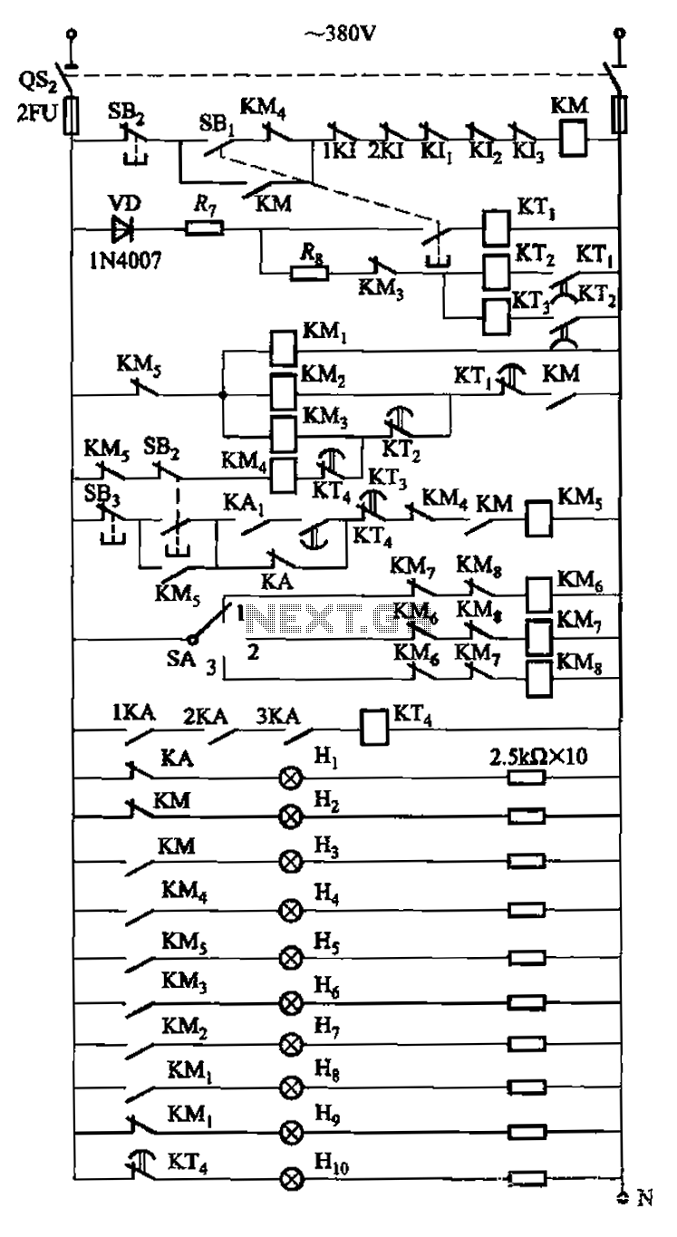
130kW induction motor synchronization control circuit operation
Circuit is shown. Motor using series resistance in the rotor winding start. Drawing, electrical velocity off the relay KIi ~ KI3 for motor short circuit protec...
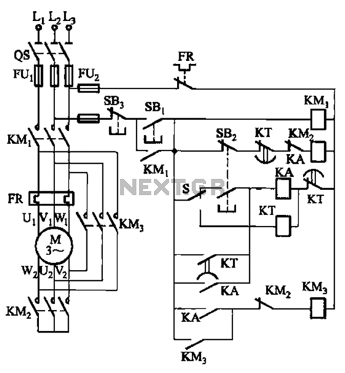
Y- buck can be manual and automatic control of the starting circuit
Circuit is shown. It can not only manually, but automatic control. ...
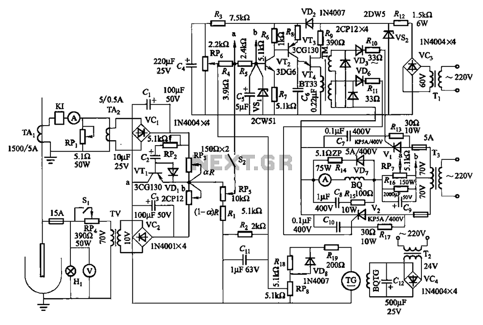
Thyristor - slip motor regulator circuit
Circuit is shown in Fig. 16-95 - 16-97. The electrode automatic adjuster has better performance. Such as the use of the accuracy high, good linearity current o...
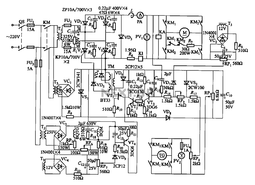
Quadruple semi-continuous casting machine speed control circuit
Circuit from the main circuit, trigger circuit, speed negative feedback, negative feedback differential voltage, current cut-off circuit, loss of field protect...

Three-phase squirrel cage motor running single phase connection circuit
Circuit connection as shown in a, b, in which a star-shaped FIG winding shunt capacitance of the connection, Fig. B triangular winding capacitance in parallel ...
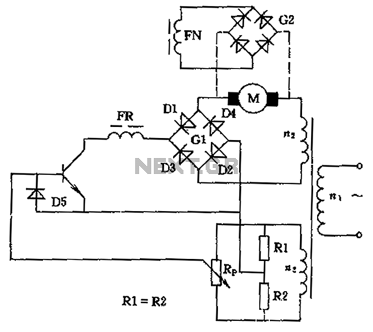
DC motor speed control circuit diagram of a song
Circuit can be used to control low power DC motor, series motor or shunt motor speed and direction. Motor and rectifier bridge G1 series, and then connected to...
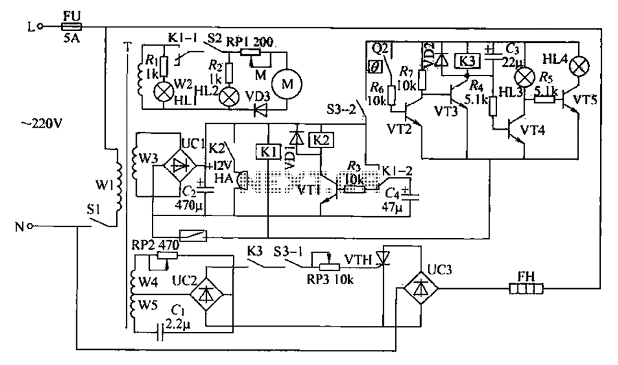
Chemical mixer circuit
Chemical mixer circuit having a stirring speed, thermostat and timer alarm function can be used in chemical, steel and other industries. (1) circuit works heat...
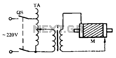
Check the circuit diagram of a three-phase motor with broken bars
Check the three-phase motor with broken bars As shown in the three-phase motor with broken bars of inspection circuit: ...
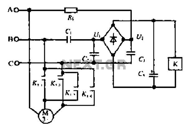
A motor reversing automatic adjustment circuit
C ,. C! Composition ratio circuit. Ri. C, constituting the shift shed circuit diode VDi - VD4 constitute destroy stream bridge, electric pit C4 is used - Appli...
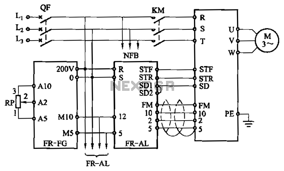
The use of FR-FG and FR-AL achieve multiple synchronous motor running circuit
By the main speed setting box FR-FG and the linkage setting operation box FR-AL (Mitsubishi inverter) multi motors synchronous operation. Circuit is shown. Usi...
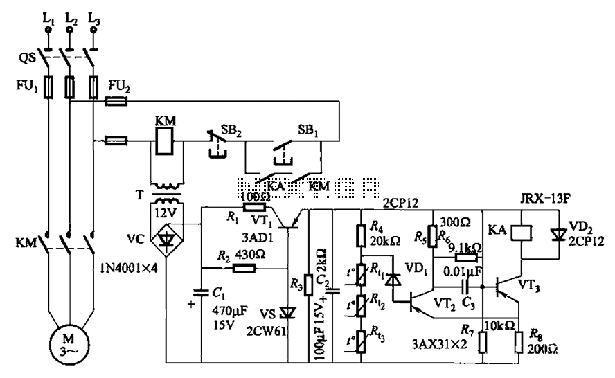
Three-phase asynchronous motor PTC protection circuits
By the PI.] P-type transistor VT2, VT3 and other components common emitter-coupled trigger (ie, Schmitt trigger device), equivalent to a switching circuit to d...
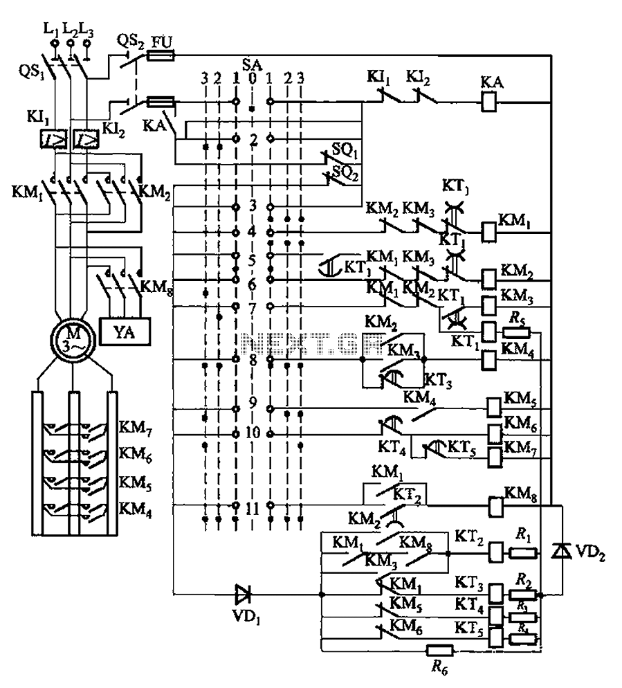
PQS1 series magnetic disk control panning control circuit
By master controller and PQS1 Series Magnetic control panel consisting of a control circuit for controlling the bridge crane hoist lifting mechanism of control...
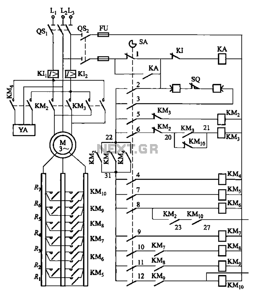
PQR10A type magnetic disk control panning control circuit
By master controller LKl-12/90 and a magnetic disk control PQR10A composed of a control circuit. Cam control device SA contact closure is shown in Table 8-5. T...
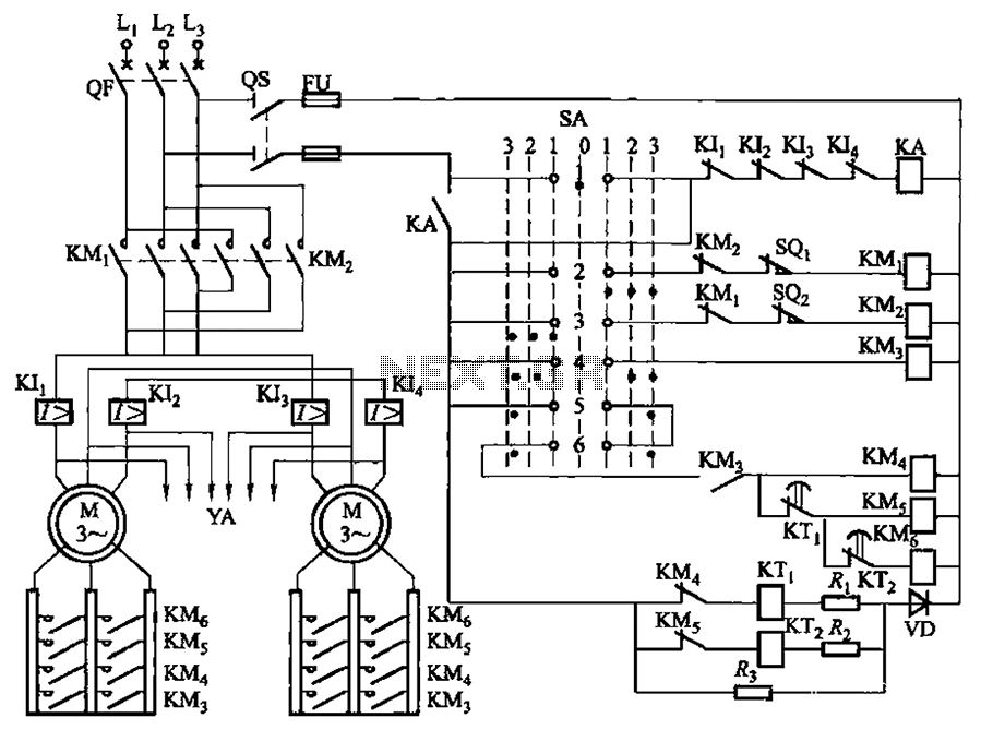
PQY2 series magnetic disk control panning control circuit
By LK16-5/31 type master controller and PQY2 Series Magnetic control panel consisting of a control circuit. The figure shows, PQY2 series control panel and mag...

PQY1 series magnetic disk control circuit control
By LK16-5/31 type master controller and PQY1 Series Magnetic control panel consisting of a control circuit. Figure, SQ1, SQ2 the motor is, reverse limit switch...