


battery eliminator circuit
#battery eliminator
#9V power supply
#LM317T
#rectification
#transformer
#voltage regulation
#filter capacitor
#bridge rectifier
#PP3 replacement
#DC power
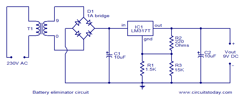
Description: This document presents a circuit diagram of a battery eliminator circuit designed to replace 9V PP3 batteries. It can power any device that operates on a 9V battery. The transformer T1 reduces the mains voltage, while bridge rectifier D1 converts the AC voltage to DC. Capacitor C1 functions as a filter, and the IC LM317T serves as the voltage regulator. Resistors R1, R2, and R3 are selected to ensure that the output voltage of the IC remains stable at 9 volts.
The battery eliminator circuit is structured to efficiently convert mains voltage into a usable 9V DC output for various electronic devices. The transformer (T1) is pivotal in this design, as it steps down the high voltage AC from the mains to a lower AC voltage suitable for rectification. Typically, a step-down transformer with a secondary output rating of around 9V to 12V is used, depending on the load requirements.
The bridge rectifier (D1), composed of four diodes arranged in a bridge configuration, performs the essential function of converting the stepped-down AC voltage into pulsating DC. This pulsating DC output is not suitable for most devices, hence the need for filtering to smooth the voltage.
Capacitor C1 acts as a smoothing filter, reducing the ripple in the DC output. The value of C1 is chosen based on the load current and the acceptable ripple voltage level; larger capacitance values will yield a smoother output, but will also increase the physical size and cost of the circuit.
The voltage regulation is handled by the LM317T integrated circuit, which is a versatile adjustable voltage regulator. It is capable of providing a stable output voltage, which is crucial for sensitive electronic devices. The output voltage can be set to 9V by selecting appropriate resistor values for R1 and R2, according to the formula provided in the LM317T datasheet. The resistor R3 can be used as a current limiting resistor or to set the minimum load current necessary for proper regulation.
In summary, this battery eliminator circuit is an effective solution for powering devices that require a 9V supply, offering a reliable and stable output while eliminating the need for disposable batteries. Proper component selection and configuration ensure that the circuit operates efficiently and meets the voltage and current requirements of the connected devices.Here is the circuit diagram of a battery eliminator circuit that can be used as a replacement for 9V PP3 batteries. The circuit given here can be used to power any device that operates from a 9V battery. The transformer T1 steps down the mains voltage and bridge D1 performs the job of rectification. Capacitor C1 is a filter. IC LM317T is the regul ator here. The value of R1, R2 and R3 are so selected that the output voltage of IC1 will be steady 9 volts.
The battery eliminator circuit is structured to efficiently convert mains voltage into a usable 9V DC output for various electronic devices. The transformer (T1) is pivotal in this design, as it steps down the high voltage AC from the mains to a lower AC voltage suitable for rectification. Typically, a step-down transformer with a secondary output rating of around 9V to 12V is used, depending on the load requirements.
The bridge rectifier (D1), composed of four diodes arranged in a bridge configuration, performs the essential function of converting the stepped-down AC voltage into pulsating DC. This pulsating DC output is not suitable for most devices, hence the need for filtering to smooth the voltage.
Capacitor C1 acts as a smoothing filter, reducing the ripple in the DC output. The value of C1 is chosen based on the load current and the acceptable ripple voltage level; larger capacitance values will yield a smoother output, but will also increase the physical size and cost of the circuit.
The voltage regulation is handled by the LM317T integrated circuit, which is a versatile adjustable voltage regulator. It is capable of providing a stable output voltage, which is crucial for sensitive electronic devices. The output voltage can be set to 9V by selecting appropriate resistor values for R1 and R2, according to the formula provided in the LM317T datasheet. The resistor R3 can be used as a current limiting resistor or to set the minimum load current necessary for proper regulation.
In summary, this battery eliminator circuit is an effective solution for powering devices that require a 9V supply, offering a reliable and stable output while eliminating the need for disposable batteries. Proper component selection and configuration ensure that the circuit operates efficiently and meets the voltage and current requirements of the connected devices.Here is the circuit diagram of a battery eliminator circuit that can be used as a replacement for 9V PP3 batteries. The circuit given here can be used to power any device that operates from a 9V battery. The transformer T1 steps down the mains voltage and bridge D1 performs the job of rectification. Capacitor C1 is a filter. IC LM317T is the regul ator here. The value of R1, R2 and R3 are so selected that the output voltage of IC1 will be steady 9 volts.
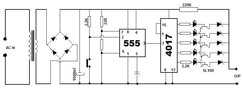
Multipurpose Battery Eliminator Circuit using 4017 Decade Counter
Battery eliminators are circuits that create a DC power supply from AC mains. Essentially, battery eliminator circuits consist of a step-down transformer, rectifier, and voltage regulator. A simple circuit of a multipurpose battery eliminator features various output voltage ranges controlled...
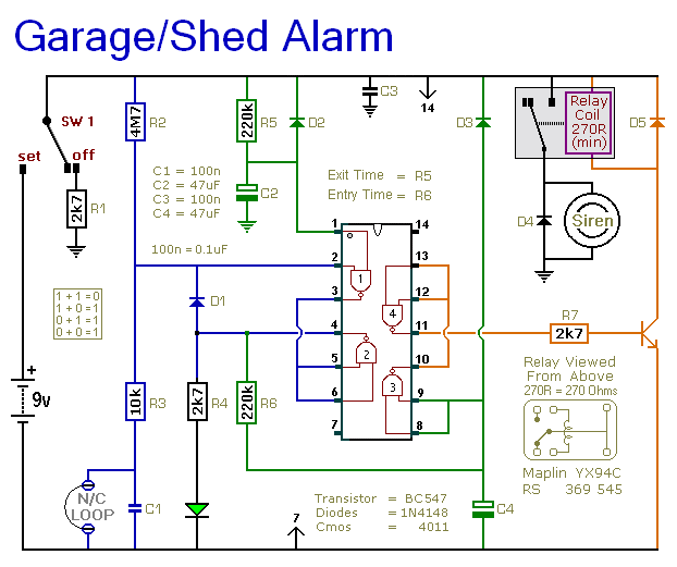
9V Power Supply For Garage Shed Alarm
The following circuit illustrates a 9V power supply for a garage shed alarm circuit diagram. Features include a single-zone burglar alarm circuit that is used with the system.
The 9V power supply circuit for the garage shed alarm is designed to...
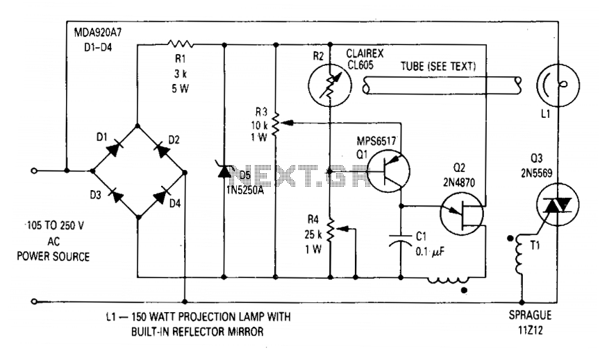
Voltage regulator for projection lamp
The circuit regulates the RMS output voltage across a load, specifically a projection lamp, to 100 volts ±2% for input voltages ranging from 105 to 250 volts AC. This regulation is achieved by indirectly sensing the light output of lamp...

DIY Circuit Car Battery Charger
This simple circuit consists of a transformer, two diodes, a capacitor, and an ammeter. To charge a battery, connect the positive and negative terminals of the circuit to the corresponding terminals of the battery. When the battery is not charged,...
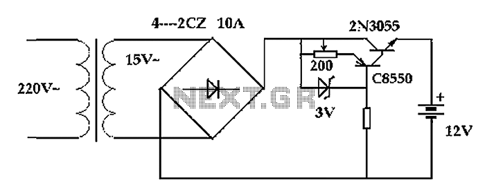
Classic car battery charging circuit diagram
The circuit operates after a transformer, utilizing a bridge rectifier and conditioning for battery charging. The charging current transformer can be easily adjusted to provide approximately 12V at 100Ah battery charging. The required charging current is 10A, and a 150VA...

psu
The Chameleon II Power Supply Circuits convert the raw input supply into stable voltage outputs necessary for the Chameleon interfaces. The outputs provided are +5V, +12V, and -12V.
The Chameleon II Power Supply Circuits are designed to ensure reliable operation of...
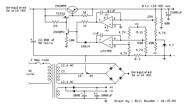
Current and Variable Voltage Power Supply
Another adjustment of application operational amplifiers to adapt a power supply is apparent below. The power supply requires an additional adjustment to supply the op-amps with a bipolar voltage (+/- 8 volts), and the negative voltage is also used to...
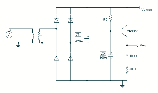
Rectification using a Gyrator Circuit
To avoid excess ripple output on a power supply feeding a heavy load, usually a large value capacitor is chosen following the rectifier. In this circuit, C1 is only a 470uF capacitor. The gyrator principle uses the effect that the...
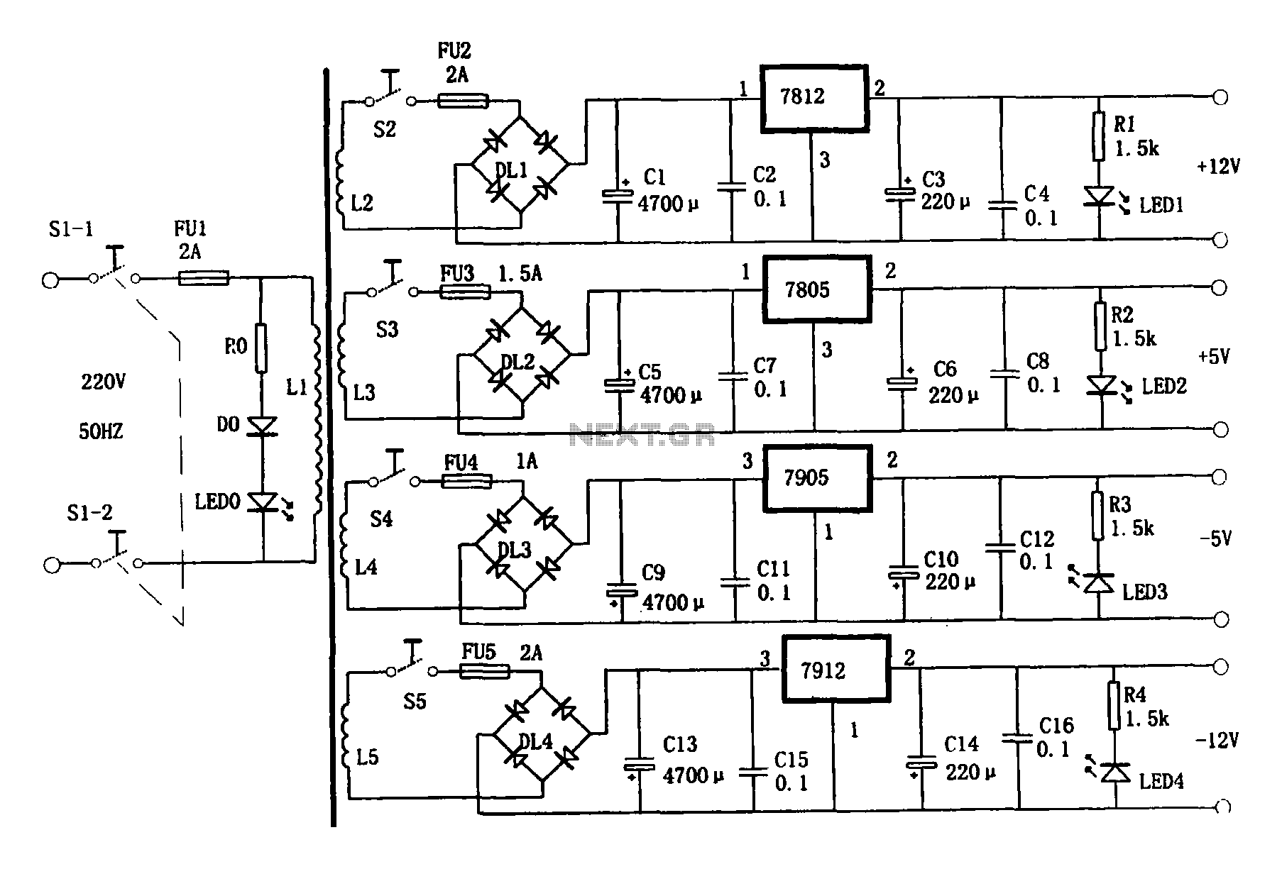
Multi-output power supply circuit
This document presents a multi-output power supply circuit. The circuit utilizes the secondary winding of a transformer and incorporates four voltage regulators: 7812, 7805, 7905, and 7912, providing independent output voltages of +12V, +5V, -5V, and -12V, respectively. Each output...