


LED Sensor Electronic Tracker with H-Bridge Drive
#LED sensor
#H-Bridge
#tracking
#surface mount
#feedback sensor
#precision
#sunlight
#active feedback
#electronic tracker
Description: I decided to make a commercial surface mount PC board using the LED2 sensor concept. It is quite sensitive and can track to a few degrees of accuracy in bright sunlight. If a blocking shadow is used the accuracy is better than 1/4 degree, that's about as good as you can get with an active feedback sensor. The board is a tiny .7"x1.4". More: This circuit uses power MOSFET drivers and is designed to operate satellite dish linear actuators, however most any DC motor can be used. The power drivers are capable of delivering about 10 amps of peak current, maybe more. When better transistors become.
The described circuit is centered around a compact surface mount printed circuit board (PCB) that integrates the LED2 sensor technology. This sensor is engineered to detect angular positions with high precision, achieving an accuracy of a few degrees under bright sunlight conditions. The performance improves significantly when a blocking shadow is introduced, enhancing the accuracy to better than 0.25 degrees. This level of precision is particularly advantageous for applications requiring active feedback mechanisms.
The PCB measures 0.7 inches by 1.4 inches, indicating a design that prioritizes space efficiency while maintaining functionality. The compact size allows for integration into various devices and applications without significant spatial constraints.
The circuit employs power MOSFET drivers, which are instrumental in controlling linear actuators commonly found in satellite dish setups. These drivers are capable of handling substantial current loads, rated at approximately 10 amps of peak current, thus providing sufficient power for driving various DC motors beyond just those used in satellite applications. The selection of MOSFETs in this design is critical, as they must be capable of managing the thermal and electrical demands of the system, especially during peak operational conditions.
In summary, this circuit configuration offers a robust solution for precise angular tracking and control, leveraging advanced sensor technology and powerful driving capabilities suitable for a wide range of applications in automation and motor control.I decided to make a commercial surface mount PC board using the LED2 sensor concept. It is quite sensitive and can track to a few degrees of accuracy in bright sunlight. If a blocking shadow is used the accuracy is better then 1/4 degree, that`s about as good as you can get with an active feedback sensor. The board is a tiny .7"x1.4". This circuit uses power MOSFET drivers and is designed to operate satellite dish linear actuators, however most any DC motor can be used. The power drivers are capable of delivering about 10 amps of peak current, maybe more. When better transistors become
The described circuit is centered around a compact surface mount printed circuit board (PCB) that integrates the LED2 sensor technology. This sensor is engineered to detect angular positions with high precision, achieving an accuracy of a few degrees under bright sunlight conditions. The performance improves significantly when a blocking shadow is introduced, enhancing the accuracy to better than 0.25 degrees. This level of precision is particularly advantageous for applications requiring active feedback mechanisms.
The PCB measures 0.7 inches by 1.4 inches, indicating a design that prioritizes space efficiency while maintaining functionality. The compact size allows for integration into various devices and applications without significant spatial constraints.
The circuit employs power MOSFET drivers, which are instrumental in controlling linear actuators commonly found in satellite dish setups. These drivers are capable of handling substantial current loads, rated at approximately 10 amps of peak current, thus providing sufficient power for driving various DC motors beyond just those used in satellite applications. The selection of MOSFETs in this design is critical, as they must be capable of managing the thermal and electrical demands of the system, especially during peak operational conditions.
In summary, this circuit configuration offers a robust solution for precise angular tracking and control, leveraging advanced sensor technology and powerful driving capabilities suitable for a wide range of applications in automation and motor control.I decided to make a commercial surface mount PC board using the LED2 sensor concept. It is quite sensitive and can track to a few degrees of accuracy in bright sunlight. If a blocking shadow is used the accuracy is better then 1/4 degree, that`s about as good as you can get with an active feedback sensor. The board is a tiny .7"x1.4". This circuit uses power MOSFET drivers and is designed to operate satellite dish linear actuators, however most any DC motor can be used. The power drivers are capable of delivering about 10 amps of peak current, maybe more. When better transistors become
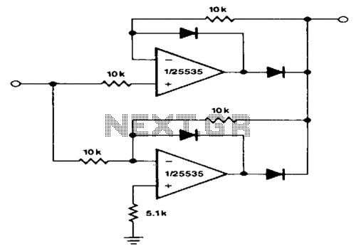
Precision-full-wave-rectifier
This circuit provides accurate full-wave rectification. The output impedance is low for both input polarities, and the errors are small at all signal levels. It is important to note that the output will not sink heavy currents, except for a...
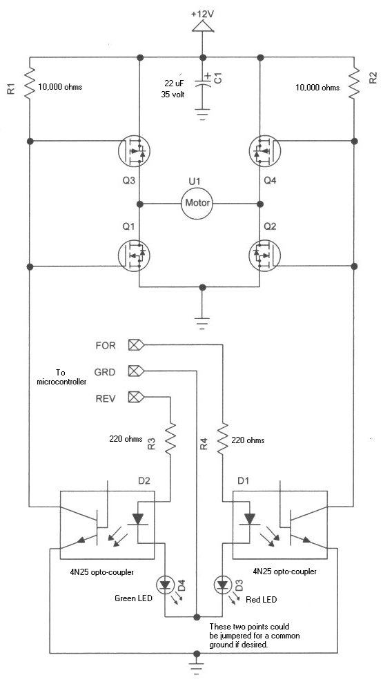
h bridge
Learning how to use power MOSFETs by building an H-bridge motor control.
The H-bridge motor control circuit is an essential configuration for driving DC motors in both forward and reverse directions. It utilizes four power MOSFETs arranged in a bridge configuration,...
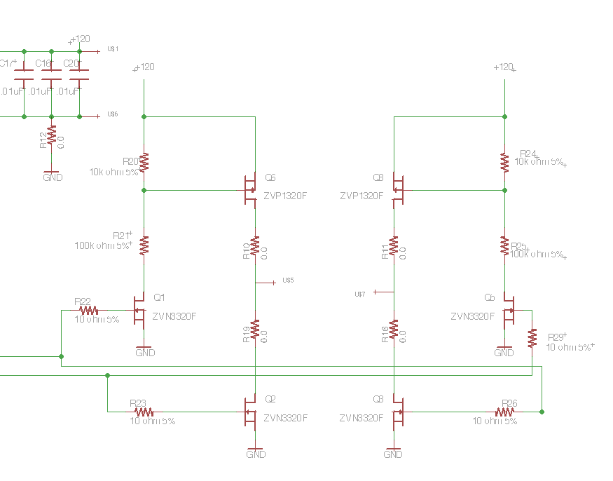
Driving a Capacitive Load with an H-bridge
Following the publication of a previous post, some unusual issues were encountered, which required several days to clarify. The main focus was on building a simple Class D amplifier designed to provide an EL panel with a +/- 120V square...
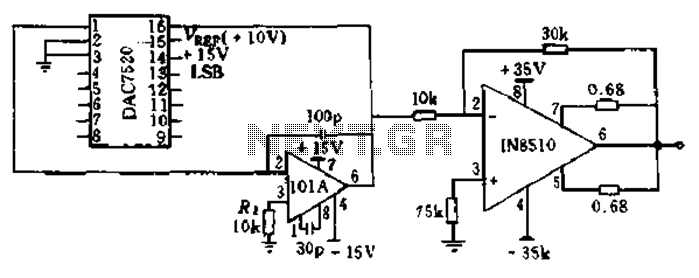
IN8510 and power motor driver circuit composed of DAC7520
The BTS412B functions as two high-side power MOSFET switches, while the BU271L components rated for 50V serve as the low-side switches. Together, these elements can form a bi-directional H-bridge DC motor drive circuit, as depicted in Figure 11-1l. This circuit...
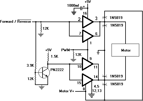
Bi-directional Control Of Motors And The H-Bridge
Reversing the DC power connections on a motor causes its shaft to rotate in the opposite direction. One method to control the direction is by using switches arranged in a specific configuration known as an H-Bridge. For instance, when the...
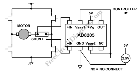
Differential Current Sensing Inside H Bridge
A differential current sensing circuit is integrated within an H-bridge configuration, as illustrated in the schematic diagram below. This circuit exemplifies the application of the AD8205, which is capable of measuring current in both directions as the motor changes direction...
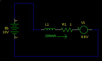
h bridge How can I implement regenerative braking of a DC motor
Many electric vehicles can convert the momentum of the car into stored energy in batteries, instead of dissipating it as heat in the brake pads. This process is known as regenerative braking. It can be implemented using a motor controlled...
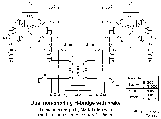
Full-featured Dual H-bridge
This is a slightly revised version of the 6-transistor H-bridge designed by Mark Tilden and found on the BEAM Tek website (now only available via archive). I encourage anyone interested in H-bridges to read Mark's article, as it gives an...
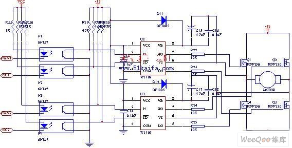
Using IRFP250 power tube H-bridge motor drive circuit
The drive circuit for the electromotor comprises a FET bridge circuit, a FET base drive circuit, a current sensor for the motor drive circuit, and a relay. The FET bridge circuit primarily consists of four high-power MOSFETs, which must possess...