spi flash programmer circuit diagram
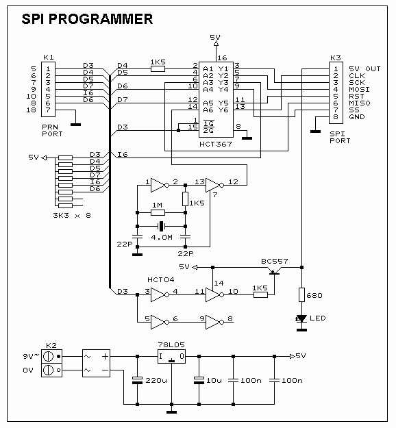
The image below displays the schematic diagram of the SPI Flash programmer hardware interface. Power for the interface can be supplied using either a 9V DC adapter or a 9V battery. The 74HCT367 integrated circuit (IC) buffers the adjacent port signals. It is essential to utilize the HCT type IC to ensure compatibility with the 3V type adjacent port. The 74HCT04 is employed to generate the clock signal for the microcontroller when programming the device in stand-alone mode.
The SPI Flash programmer hardware interface is designed to facilitate the programming of flash memory devices using the Serial Peripheral Interface (SPI) protocol. The power supply options, either a 9V DC adapter or a 9V battery, provide flexibility in various operational environments, ensuring that the programmer can function effectively in both stationary and portable applications.
The 74HCT367 IC serves as a buffer for the signals coming from the adjacent ports. This buffering is crucial to maintain signal integrity, especially when interfacing with devices that operate at different voltage levels. The HCT series of ICs is specifically chosen for their compatibility with both 5V and 3V logic levels, which is vital for ensuring that the programmer can interact seamlessly with various microcontroller architectures.
The 74HCT04, a hex inverter, is used to generate the necessary clock signal for the microcontroller during the programming process. This clock signal is critical for synchronizing data transfer between the programmer and the flash memory device. In stand-alone mode, the microcontroller relies on this clock signal to execute the programming commands accurately and efficiently.
Overall, the design of the SPI Flash programmer hardware interface emphasizes versatility, ensuring compatibility with multiple voltage levels and providing reliable operation for programming flash memory devices. The careful selection of components, such as the 74HCT367 and 74HCT04, underscores the importance of maintaining signal integrity and operational reliability in various programming scenarios.The Picture beneath is shows the ambit diagram of the SPI Flash programmer accouterments interface, the ability to the interface is provided either by a 9V dc adapter or a 9V battery. The 74HCT367 IC absorber the alongside anchorage signals. It is all-important to use the HCT blazon IC in adjustment to accomplish abiding the programmer should addi
tionally assignment with the 3V blazon alongside port. The 74HCT04 is acclimated to accomplish the alarm arresting for the u-controller back programming the accessory in stand-alone mode. 🔗 External reference
